
pIR Sensor
Model: T2600
- TT-pIR iHeadband includes 2 TT-Infra sensors to monitor temperature from the forehead without direct contact.
Product Overview
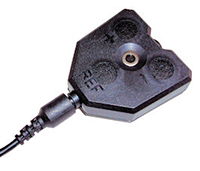 The pIR sensor is a passive infrared temperature sensor for measuring radiated temperature in the infrared range. It is used to measure the changes in forehead temperature when attached to the pIR HEadGear™.
Passive infrared temperature is measured in degrees Celsius or degrees Fahrenheit.
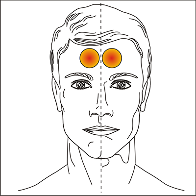 Area of interest: The pIR sensor is designed to be used in pairs and fixed to the pIR HEadGearTM, such that the forehead region shown in the diagram to the right is adequately monitored.
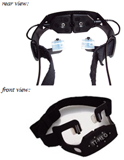 pIR HEadGear™: The headgear is made of thin, lightweight plastic and holds two adjacent pIR sensors in the configuration shown to the right (see rear view).
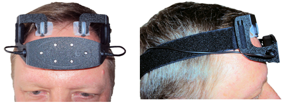
It should be placed on the forehead with the strap adjusted for stability and comfort. The location should be such that the sensor view should cover the forehead region of interest shown above. The images below show the ideal location of the head gear.
Technical Specifications
- Size (approx.) : 37mm x 37mm x 12mm (1.45” x 1.45” x .45”)
- Weight (approx.) : 12.5g (0.5oz)
- Absolute measurement accuracy : ± 0.5C
- Measurement Resolution : 0.02C
- Measurement range : 19.76C – 40.24C
- Operating Temperature (room ambient) : 20C - 30C
- Target emissivity : 98.0%
- Sensor warm-up time : 60 seconds
- Supply voltage : 7.26V
- Max. supply current : 2.5mA
Interfacing with 3rd Party Data Acquisition Systems
Recommended Connectivity for Electrical Safety
Thought Technology recommends the use of TT Sensor Isolator ST9405AM when interfacing patient connected sensor(s) to line powered equipment(s) or devices.
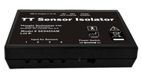 The TT Sensor Isolator ST9405AM is an interface device providing medical grade electrical isolation between the patient connected sensors and the acquisition system. It provides the equivalent of Two Means of Patient Protection under IEC 60601-1, and supplies battery power to the sensors. Using this device ensures Thought Technology sensors are safely interfaced to the analog inputs of line-powered systems such as computers with DAQ cards.
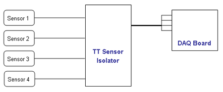
Note that this device isolates only between sensors and the DAQ interface, not between different sensor channels.
The TT Sensor Isolator can interface up to 4 sensors to a DAQ card. TT Sensor Isolator can be connected to the DAQ card in two ways:
- via two stereo jacks, or
- via a DB-15 connector; a BNC interface cable (SA9409BNC) or a pigtail cable (SA9409PGT) can be provided with the unit.
For more detailed information on the Sensor Isolator 4∞, consult the Thought Technology Science Division website or contact the sales department or your distributor.
Division website or contact the sales department or your distributor.
Direct Connectivity for Electrically Isolated Systems
The following notes are provided for qualified users to directly interface Thought Technology sensors with external systems.
WARNING: If the sensor is interfaced to non-Thought Technology devices without the use of a TT Sensor Isolator SE9405AM, an elevated risk of electrical shock may be present. In particular, if a patient-connected sensor is connected to any line powered device(s) or equipment(s), it will be the responsibility of the qualified user to ensure the electrical safety in the setup and to ensure that the device or equipment provides sufficient isolation.
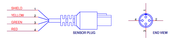
To interface with a sensor, a single sensor cable may be cut in half. Both sides can then be used to make custom interfacing cables by stripping the outer insulation of each required conductor. The sensor cable contains 4 color coded conductors. The table below shows the color coding and pin connector assignment.
| Pin | Color Code | Function | Note |
| 1 | metal (shield) | ground | Signal and power ground, connection required. |
| 2 | yellow | auxiliary (sensor ID) | No connection required. |
| 3 | green | signal | Sensor output signal |
| 4 | red | sensor power | Supply voltage, +7.26V referenced to ground. Note: sensor performance may be sensitive to supply voltage. |
Notes:
1. The nominal supply voltage for this sensor is 7.26V. The sensor can safely be used with a supply voltage of up to 9V.
Recommended Specifications for DAQ Hardware
- Recommended resolution of 0.15mV (16-bit ADC over 10V span) or better
- Minimum input range:
- If connected via SE9405AM Sensor Isolator, choose 0-5V (unipolar) or ±5V (bipolar).
- If directly connected to DAQ, choose ±5V (bipolar).
Simplified Transfer Function
![]() Temperature in Celsius to output voltage in volts.
Temperature in Celsius to output voltage in volts.
![]() Voltage [V] conversion to temperature [ºC]
Voltage [V] conversion to temperature [ºC]
![]() Voltage [V] conversion to temperature [ºF]
Voltage [V] conversion to temperature [ºF]
Product Overview
The pIR sensor is a passive infrared temperature sensor for measuring radiated temperature in the infrared range. It is used to measure the changes in forehead temperature when attached to the pIR HEadGear™.
Passive infrared temperature is measured in degrees Celsius or degrees Fahrenheit.
Area of interest: The pIR sensor is designed to be used in pairs and fixed to the pIR HEadGearTM, such that the forehead region shown in the diagram to the right is adequately monitored.
pIR HEadGear™: The headgear is made of thin, lightweight plastic and holds two adjacent pIR sensors in the configuration shown to the right (see rear view).
It should be placed on the forehead with the strap adjusted for stability and comfort. The location should be such that the sensor view should cover the forehead region of interest shown above. The images below show the ideal location of the head gear.
Technical Specifications
- Size (approx.) : 37mm x 37mm x 12mm (1.45” x 1.45” x .45”)
- Weight (approx.) : 12.5g (0.5oz)
- Absolute measurement accuracy : ± 0.5C
- Measurement Resolution : 0.02C
- Measurement range : 19.76C – 40.24C
- Operating Temperature (room ambient) : 20C - 30C
- Target emissivity : 98.0%
- Sensor warm-up time : 60 seconds
- Supply voltage : 7.26V
- Max. supply current : 2.5mA
Interfacing with 3rd Party Data Acquisition Systems
Recommended Connectivity for Electrical Safety
Thought Technology recommends the use of TT Sensor Isolator ST9405AM when interfacing patient connected sensor(s) to line powered equipment(s) or devices.
The TT Sensor Isolator ST9405AM is an interface device providing medical grade electrical isolation between the patient connected sensors and the acquisition system. It provides the equivalent of Two Means of Patient Protection under IEC 60601-1, and supplies battery power to the sensors. Using this device ensures Thought Technology sensors are safely interfaced to the analog inputs of line-powered systems such as computers with DAQ cards.
Note that this device isolates only between sensors and the DAQ interface, not between different sensor channels.
The TT Sensor Isolator can interface up to 4 sensors to a DAQ card. TT Sensor Isolator can be connected to the DAQ card in two ways:
- via two stereo jacks, or
- via a DB-15 connector; a BNC interface cable (SA9409BNC) or a pigtail cable (SA9409PGT) can be provided with the unit.
For more detailed information on the Sensor Isolator 4∞, consult the Thought Technology Science Division website or contact the sales department or your distributor.
Division website or contact the sales department or your distributor.
Direct Connectivity for Electrically Isolated Systems
The following notes are provided for qualified users to directly interface Thought Technology sensors with external systems.
WARNING: If the sensor is interfaced to non-Thought Technology devices without the use of a TT Sensor Isolator SE9405AM, an elevated risk of electrical shock may be present. In particular, if a patient-connected sensor is connected to any line powered device(s) or equipment(s), it will be the responsibility of the qualified user to ensure the electrical safety in the setup and to ensure that the device or equipment provides sufficient isolation.
To interface with a sensor, a single sensor cable may be cut in half. Both sides can then be used to make custom interfacing cables by stripping the outer insulation of each required conductor. The sensor cable contains 4 color coded conductors. The table below shows the color coding and pin connector assignment.
| Pin | Color Code | Function | Note |
| 1 | metal (shield) | ground | Signal and power ground, connection required. |
| 2 | yellow | auxiliary (sensor ID) | No connection required. |
| 3 | green | signal | Sensor output signal |
| 4 | red | sensor power | Supply voltage, +7.26V referenced to ground. Note: sensor performance may be sensitive to supply voltage. |
Notes:
1. The nominal supply voltage for this sensor is 7.26V. The sensor can safely be used with a supply voltage of up to 9V.
Recommended Specifications for DAQ Hardware
- Recommended resolution of 0.15mV (16-bit ADC over 10V span) or better
- Minimum input range:
- If connected via SE9405AM Sensor Isolator, choose 0-5V (unipolar) or ±5V (bipolar).
- If directly connected to DAQ, choose ±5V (bipolar).
Simplified Transfer Function
![]() Temperature in Celsius to output voltage in volts.
Temperature in Celsius to output voltage in volts.
![]() Voltage [V] conversion to temperature [ºC]
Voltage [V] conversion to temperature [ºC]
![]() Voltage [V] conversion to temperature [ºF]
Voltage [V] conversion to temperature [ºF]
Technical Specifications
| Size (approx.) :37mm x 37mm x 12mm (1.45” x 1.45” x .45”) |
| Weight (approx.) :12.5g (0.5oz) |
| Absolute measurement accuracy :± 0.5C |
| Measurement Resolution :0.02C |
| Measurement range :19.76C – 40.24C |
| Operating Temperature (room ambient) :20C - 30C |
| Target emissivity :98.0% |
| Sensor warm-up time : 60 seconds |
| Supply voltage : 7.26V |
| Max. supply current : 2.5mA |
More Products to Consider
 TT Infra Sensor
Table of Contents
Suggested References