
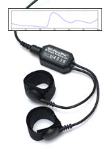
SKIN CONDUCTANCE SENSOR
Model: SA9309M
- SC-Flex/Pro is a Skin Conductance sensor which measures the conductance across the skin. It comes with 2 finger bands.
Product Overview
 The Skin Conductance Sensor measures electrical conductance between two points on the skin, and is normally connected to the fingers or toes. It is supplied with two finger bands.
 Skin conductance (SC) is an index of sympathetic nervous system (SNS) activation and emotional arousal. To measure skin conductance, a small electrical potential is applied between two electrodes strapped or taped to the palmar side of the hand, and the amount of current conducted between the electrodes is measured.
 Although the exact physiological mechanism is not completely understood, it is generally accepted that SC varies directly with the amount of sweat secreted by the skin and indirectly with the number of sweat glands that are activated by the SNS. Biofeedback applications of SC generally involve reducing stress levels and training adaptability. SC is also useful for evaluating the effectiveness of relaxation practices. As the amount of stress increases, so does the skin conductance level. Relaxation decreases SC. Because it is highly sensitive to instantaneous emotional changes, SC is frequently used to reflect such reactions as anger, fear, or sexual feelings and to measure the startle response (response to a visual or auditory stimulus). SC is also an important component in lie detection systems (polygraphs).
Sensor Placement
 There are two finger straps attached to the skin conductance sensor.
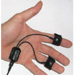
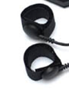
The conductive electrode in each finger strap should be placed against the inside part of the finger.
A good choice for placement is to use the index and ring finger. Close the hook and loop fasteners around the fingers so that contact is snug yet comfortable.
Placement with the cables directed inwards (shown) is practical for keeping the cables out of the way.
Using multiple sensors together:
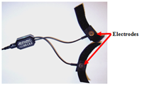
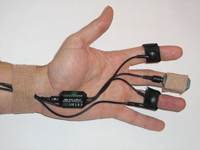 This configuration is suggested for placing skin conductance, BVP and temperature sensors on the same hand. In this configuration, the temperature sensor (SA9310M) is tucked under the ring finger strap of the skin conductance sensor.
This is a practical way to combine these sensors, but care must be taken to ensure that the end of the temperature sensor is secured firmly against the skin.
Also note that the cables are all directed inwards and Coban tape is used to secure the cables to the wrist.
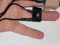 Close up view of temperature sensor and skin conductance finger strap.
Technical Specifications
- Size (spprox.) : 37 mm x 37 mm x 12 mm (1.45” x 1.45” x 0.45”)
- Weight (spprox.) : 25g (1.0 oz)
- Input Impedance : 10¹²Ω in parallel with 10pF
- Operating Input Bias : ~ 1.0 to 2.0 V above sensor ground
- Signal Input Range : ± 40 mV
- Channel Bandwidth : 0.05 Hz - 1 kHz
- Signal Output Range : ± 2.0 V (+ 2.8 V if used with Sensor Isolator)
- Input / Output Gain : 50
- Supply Voltage : 7.26 V (±0.05 V)
- Current Consumption : < 1.5 mA
- Accuracy : ± 5%
ELECTRICAL COMPATIBILITY
The SA9309M Skin Conductance sensor is designed to coexist with other Thought Technology bio potential sensors such as T9305M EEG sensor, T7680 EEG-Z3 sensor, T9303M MyoScan sensor, or T9306 (or T9307) EKG sensor.
To ensure correct Skin Conductance sensor operation, if sensors from another manufacturer are in the same electrical circuit and connected to the same subject, their electrodes must function at a voltage within the specified operating bias range, 1.0 to 3.0 volts above sensor ground. To check whether another sensor is interfering with the Skin Conductance sensor operation, connect and disconnect the other sensor from the subject, and note whether this causes a change in the Skin Conductance sensor signal level, or whether connection of the other sensor appears to cause any signal artifacts in the Skin Conductance signal.
Interfacing with 3rd Party Data Acquisition Systems
Recommended Connectivity for Electrical Safety
Thought Technology recommends the use of TT Sensor Isolator ST9405AM when interfacing patient connected sensor(s) to line powered equipment(s) or devices.
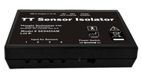 The TT Sensor Isolator ST9405AM is an interface device providing medical grade electrical isolation between the patient connected sensors and the acquisition system. It provides the equivalent of Two Means of Patient Protection under IEC 60601-1, and supplies battery power to the sensors. Using this device ensures Thought Technology sensors are safely interfaced to the analog inputs of line-powered systems such as computers with DAQ cards.
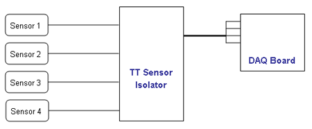
Note that this device isolates only between sensors and the DAQ interface, not between different sensor channels.
The TT Sensor Isolator can interface up to 4 sensors to a DAQ card. TT Sensor Isolator can be connected to the DAQ card in two ways:
- via two stereo jacks, or
- via a DB-15 connector; a BNC interface cable (SA9409BNC) or a pigtail cable (SA9409PGT) can be provided with the unit.
For more detailed information on the Sensor Isolator 4∞, consult the Thought Technology Science Division website or contact the sales department or your distributor.
Division website or contact the sales department or your distributor.
Direct Connectivity for Electrically Isolated Systems
The following notes are provided for qualified users to directly interface Thought Technology sensors with external systems.
WARNING: If the sensor is interfaced to non-Thought Technology devices without the use of a TT Sensor Isolator SE9405AM, an elevated risk of electrical shock may be present. In particular, if a patient-connected sensor is connected to any line powered device(s) or equipment(s), it will be the responsibility of the qualified user to ensure the electrical safety in the setup and to ensure that the device or equipment provides sufficient isolation.
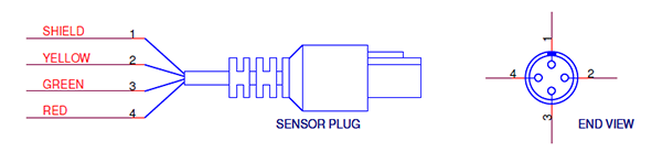
To interface with a sensor, a single sensor cable may be cut in half. Both sides can then be used to make custom interfacing cables by stripping the outer insulation of each required conductor. The sensor cable contains 4 color coded conductors. The table below shows the color coding and pin connector assignment.
| Pin | Color Code | Function | Note |
| 1 | metal (shield) | ground | Signal and power ground, connection required. |
| 2 | yellow | auxiliary (sensor ID) | No connection required. |
| 3 | green | signal | Sensor output signal |
| 4 | red | sensor power | Supply voltage, +7.26V referenced to ground. Note: sensor performance may be sensitive to supply voltage. |
Notes:
1. The nominal supply voltage for this sensor is 7.26V. The sensor can safely be used with a supply voltage of up to 9V. However, as the sensor is calibrated with a 7.26V supply voltage level, changes in gain and offset may be expected when operating at a different supply voltage level, changes in gain and offset may be expected when operating at a different supply voltage.
Recommended Specifications for DAQ Hardware
- Recommended resolution of 0.15mV (16-bit ADC over 10V span) or better
- Minimum input range:
- If connected via SE9405AM Sensor Isolator, choose 0-5V (unipolar) or ±5V (bipolar).
- If directly connected to DAQ, choose ±5V (bipolar).
Simplified Transfer Function
![]() Conversion of voltage [V] to BVP%
(for quantitative purposes only)
Conversion of voltage [V] to BVP%
(for quantitative purposes only)
![]() Conversion of voltage [v] to conductance [micro Siemens]
Conversion of voltage [v] to conductance [micro Siemens]
The simplified transfer function assumes the sensor is used with the Sensor Isolator, or the supply voltage provided in the user setup is 7.26V nominal.
Specification Summaries Of Supported Accessories / Hardware
Table below lists Thought Technology accessories for the MyoScan Pro.
| Accessory |
Product Number |
 |
SA2659 - Ag-AgCl FINGERBAND ELECTRODE |
 |
T3425 – UniGel electrodes (single use): The UniGel electrodes are a good alternative to the finger band electrodes if the sensor is not positioned on the fingers (palm of the hand, foot tec …) |
Product Overview
The Skin Conductance Sensor measures electrical conductance between two points on the skin, and is normally connected to the fingers or toes. It is supplied with two finger bands.
Skin conductance (SC) is an index of sympathetic nervous system (SNS) activation and emotional arousal. To measure skin conductance, a small electrical potential is applied between two electrodes strapped or taped to the palmar side of the hand, and the amount of current conducted between the electrodes is measured.
Although the exact physiological mechanism is not completely understood, it is generally accepted that SC varies directly with the amount of sweat secreted by the skin and indirectly with the number of sweat glands that are activated by the SNS. Biofeedback applications of SC generally involve reducing stress levels and training adaptability. SC is also useful for evaluating the effectiveness of relaxation practices. As the amount of stress increases, so does the skin conductance level. Relaxation decreases SC. Because it is highly sensitive to instantaneous emotional changes, SC is frequently used to reflect such reactions as anger, fear, or sexual feelings and to measure the startle response (response to a visual or auditory stimulus). SC is also an important component in lie detection systems (polygraphs).
Sensor Placement
There are two finger straps attached to the skin conductance sensor.
The conductive electrode in each finger strap should be placed against the inside part of the finger.
A good choice for placement is to use the index and ring finger. Close the hook and loop fasteners around the fingers so that contact is snug yet comfortable.
Placement with the cables directed inwards (shown) is practical for keeping the cables out of the way.
Using multiple sensors together:
This configuration is suggested for placing skin conductance, BVP and temperature sensors on the same hand. In this configuration, the temperature sensor (SA9310M) is tucked under the ring finger strap of the skin conductance sensor.
This is a practical way to combine these sensors, but care must be taken to ensure that the end of the temperature sensor is secured firmly against the skin.
Also note that the cables are all directed inwards and Coban tape is used to secure the cables to the wrist.
Close up view of temperature sensor and skin conductance finger strap.
Technical Specifications
- Size (spprox.) : 37 mm x 37 mm x 12 mm (1.45” x 1.45” x 0.45”)
- Weight (spprox.) : 25g (1.0 oz)
- Input Impedance : 10¹²Ω in parallel with 10pF
- Operating Input Bias : ~ 1.0 to 2.0 V above sensor ground
- Signal Input Range : ± 40 mV
- Channel Bandwidth : 0.05 Hz - 1 kHz
- Signal Output Range : ± 2.0 V (+ 2.8 V if used with Sensor Isolator)
- Input / Output Gain : 50
- Supply Voltage : 7.26 V (±0.05 V)
- Current Consumption : < 1.5 mA
- Accuracy : ± 5%
ELECTRICAL COMPATIBILITY
The SA9309M Skin Conductance sensor is designed to coexist with other Thought Technology bio potential sensors such as T9305M EEG sensor, T7680 EEG-Z3 sensor, T9303M MyoScan sensor, or T9306 (or T9307) EKG sensor.
To ensure correct Skin Conductance sensor operation, if sensors from another manufacturer are in the same electrical circuit and connected to the same subject, their electrodes must function at a voltage within the specified operating bias range, 1.0 to 3.0 volts above sensor ground. To check whether another sensor is interfering with the Skin Conductance sensor operation, connect and disconnect the other sensor from the subject, and note whether this causes a change in the Skin Conductance sensor signal level, or whether connection of the other sensor appears to cause any signal artifacts in the Skin Conductance signal.
Interfacing with 3rd Party Data Acquisition Systems
Recommended Connectivity for Electrical Safety
Thought Technology recommends the use of TT Sensor Isolator ST9405AM when interfacing patient connected sensor(s) to line powered equipment(s) or devices.
The TT Sensor Isolator ST9405AM is an interface device providing medical grade electrical isolation between the patient connected sensors and the acquisition system. It provides the equivalent of Two Means of Patient Protection under IEC 60601-1, and supplies battery power to the sensors. Using this device ensures Thought Technology sensors are safely interfaced to the analog inputs of line-powered systems such as computers with DAQ cards.
Note that this device isolates only between sensors and the DAQ interface, not between different sensor channels.
The TT Sensor Isolator can interface up to 4 sensors to a DAQ card. TT Sensor Isolator can be connected to the DAQ card in two ways:
- via two stereo jacks, or
- via a DB-15 connector; a BNC interface cable (SA9409BNC) or a pigtail cable (SA9409PGT) can be provided with the unit.
For more detailed information on the Sensor Isolator 4∞, consult the Thought Technology Science Division website or contact the sales department or your distributor.
Division website or contact the sales department or your distributor.
Direct Connectivity for Electrically Isolated Systems
The following notes are provided for qualified users to directly interface Thought Technology sensors with external systems.
WARNING: If the sensor is interfaced to non-Thought Technology devices without the use of a TT Sensor Isolator SE9405AM, an elevated risk of electrical shock may be present. In particular, if a patient-connected sensor is connected to any line powered device(s) or equipment(s), it will be the responsibility of the qualified user to ensure the electrical safety in the setup and to ensure that the device or equipment provides sufficient isolation.
To interface with a sensor, a single sensor cable may be cut in half. Both sides can then be used to make custom interfacing cables by stripping the outer insulation of each required conductor. The sensor cable contains 4 color coded conductors. The table below shows the color coding and pin connector assignment.
| Pin | Color Code | Function | Note |
| 1 | metal (shield) | ground | Signal and power ground, connection required. |
| 2 | yellow | auxiliary (sensor ID) | No connection required. |
| 3 | green | signal | Sensor output signal |
| 4 | red | sensor power | Supply voltage, +7.26V referenced to ground. Note: sensor performance may be sensitive to supply voltage. |
Notes:
1. The nominal supply voltage for this sensor is 7.26V. The sensor can safely be used with a supply voltage of up to 9V. However, as the sensor is calibrated with a 7.26V supply voltage level, changes in gain and offset may be expected when operating at a different supply voltage level, changes in gain and offset may be expected when operating at a different supply voltage.
Recommended Specifications for DAQ Hardware
- Recommended resolution of 0.15mV (16-bit ADC over 10V span) or better
- Minimum input range:
- If connected via SE9405AM Sensor Isolator, choose 0-5V (unipolar) or ±5V (bipolar).
- If directly connected to DAQ, choose ±5V (bipolar).
Simplified Transfer Function
![]() Conversion of voltage [V] to BVP%
(for quantitative purposes only)
Conversion of voltage [V] to BVP%
(for quantitative purposes only)
![]() Conversion of voltage [v] to conductance [micro Siemens]
Conversion of voltage [v] to conductance [micro Siemens]
The simplified transfer function assumes the sensor is used with the Sensor Isolator, or the supply voltage provided in the user setup is 7.26V nominal.
Specification Summaries Of Supported Accessories / Hardware
Table below lists Thought Technology accessories for the MyoScan Pro.
| Accessory |
Product Number |
|
SA2659 - Ag-AgCl FINGERBAND ELECTRODE |
|
T3425 – UniGel electrodes (single use): The UniGel electrodes are a good alternative to the finger band electrodes if the sensor is not positioned on the fingers (palm of the hand, foot tec …) |
Technical Specifications
| Size (spprox.) :37 mm x 37 mm x 12 mm (1.45” x 1.45” x 0.45”) |
| Weight (spprox.) :25g (1.0 oz) |
| Input Impedance :10¹²Ω in parallel with 10pF |
| Operating Input Bias :~ 1.0 to 2.0 V above sensor ground |
| Signal Input Range :± 40 mV |
| Channel Bandwidth :0.05 Hz - 1 kHz |
| Signal Output Range :± 2.0 V (+ 2.8 V if used with Sensor Isolator) |
| Input / Output Gain : 50 |
| Supply Voltage : 7.26 V (±0.05 V) |
| Current Consumption : < 1.5 mA |
| Accuracy : ± 5% |
More Products to Consider
 TT Infra Sensor
Table of Contents
Suggested References