
TT Sensor Isolator
Model: T9405AM
- TT Sensor Isolator is a four channel optical isolator that provides isolated analog outputs to data acquisition systems from the Thought Technology sensors that make human skin contact.
- It is available with stripped wires at the end of a 48” (120 cm) cable. Multiple isolators can be stacked for additional isolated channels.
Functional Description
1. Overview
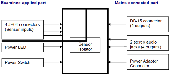
There are two parts of the Sensor Isolator circuit which are isolated from each other:
- the examinee-applied part.
- the mains-connected part.
 To operate the Sensor Isolator, each area requires a separate power source:
Client-applied area
- 9V battery (standard PP3)
Mains-connected area (powered from either of the two inputs)
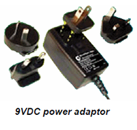
- 9VDC power adaptor
- 9VDC via DB-15 from external system
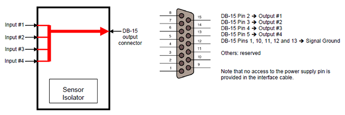
The Sensor Isolator has 4 inputs. These inputs can be connected to any Thought Technology sensors, such as, but not limited to, EMG, EKG or EEG sensors.
The Sensor Isolator has 4 outputs. The output range is 2.8V ± 1.5V.
These outputs can be connected to a data acquisition system in two ways:
- via the two stereo jacks, or
- via the DB-15 connector (interface cable provided with the unit).
2. Overview
All of the outputs are on the same circuits and the grounds are connected together :
- If connecting several outputs to the same device, only one ground connection may be required.
- If connecting outputs to more than one device ensure that no significant voltage exists between device grounds. Otherwise ground loop currents could flow through the Sensor Isolator, which could affect signal integrity or, in extreme cases, damage equipment.
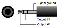
2.1 Jacks
The jacks of the Sensor Isolator are 3.5mm stereo female mini-jacks.
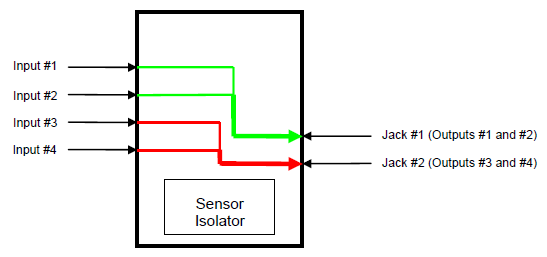
Jack #1 is connected to Output #1 and #2
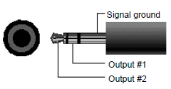
Jack #2 is connected to Output #3 and #4
2.2 DB-15 connector
The DB-type output connector of the Sensor Isolator is a DB-15 female.
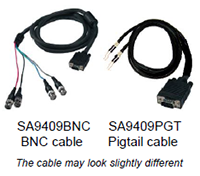
NOTE: each interfaced system will require its own cable.
Therefore we provide only a cable with BNC connectors or the pigtail cable, which are the most common ones.
Set-Up for T9405 Sensor Isolator
1. Power
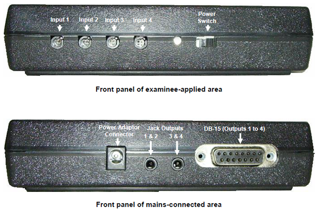
- 1.1 Powering the Examinee-Applied Area
The examinee-applied area is powered by a 9V battery.
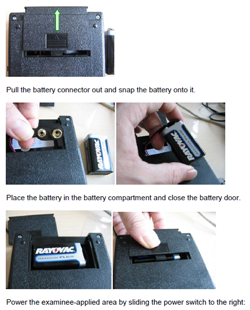
Open the battery door on the back of the unit, by applying a gentle pressure and pushing it in the direction shown by the arrow:
- 1.2 Powering the Mains-Applied Area
The mains-applied area can be powered either by the provided power adaptor or by the interfaced system via the DB15 connector.
Connect the power cable to the power connector located on the mains-applied area front panel.

No switch needs to be turned on.
For powering via the DB15, please read the previous section regarding the DB15 connector.
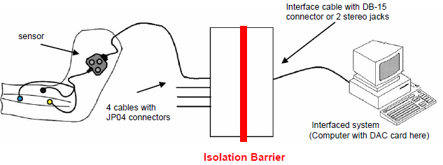
2. Cables
Here is an overview of the set-up.
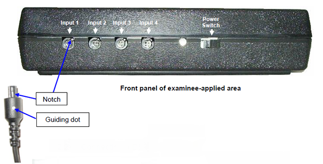
2.1 Connecting a Sensor Cable
When connecting a sensor to the Sensor Isolator, make sure to properly line up the guiding dot on the top of the plug with the notch in the device's input socket.
2.2 Connecting a DB-15 cable
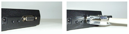
The DB15 connector is located on the mains-applied area front panel.
2.3 Connecting an audio jack
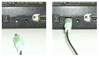
The audio jacks are located on the mains-applied area front panel, between the power connector and the DB15 connector.
T9405AM SENSOR ISOLATOR SPECIFICATIONS
- Size : 5.7 x 3.6 x 1.2 in (14.5 x 9 x 3 cm)
- Weight : 180g
- Isolation Voltage : 4.5kVrms
- Voltage Input Range : 2.8V ± 1.5V
- Bandwidth : 0 – 1kHz
- Voltage Output Range, normal : 2.8V ± 1.5V
- Voltage Output Range (possible) : 0 – 9V (connected device should tolerate this range)
- Input impedance : 1.81MΩ
- Output impedance : 110Ω
- Accuracy : Gain: ±0.1%
Offset < 1mV - Noise : <100μV RMS
- Temperature range (operating) : 10 - 40 ˚C
- Crosstalk : < -90dB or better
- Power supply : Isolated area
Examinee-applied part: 9V Alkaline battery (6LR61)
Battery Life: 10 hours typical
Low battery threshold: 7.25V
Mains-connected part: 9V AC adapter
SE9408 POWER ADAPTER SPECIFICATIONS
- GlobTek GTM41076-0609 : 6 Watts, Wall Plug-In, Switch mode Power Supply, Medical, Class II
- Input Voltage : 100-240 VAC
- Input Current : < 0.5 A RMS MAX
- Input Frequency : 47 - 63 Hz
- Output Voltage : 9V
- Output Current : 0 - 0.66A
- Output Power (Rated) : 0 - 6W
- Safety Approvals : UL60601-1, CUL to 22.2 No. 601.1-M90, INNOVA BAUART to EN60601-1, CE
CLASS II, PSE to J60601-1, CB REPORT, CTICK to AS/NZ 60601-1, CCC - Restriction of Hazardous Substances (RoHS) : Complies with EU 2002/95/EC and CHINA SJ/T 11363-2006
- Operating Temperature : 0°C to 40° C
- Storage Temperature : -40°C to 80° C
- Humidity : 0% to 90% Relative Humidity
Functional Description
1. Overview
There are two parts of the Sensor Isolator circuit which are isolated from each other:
- the examinee-applied part.
- the mains-connected part.
To operate the Sensor Isolator, each area requires a separate power source:
Client-applied area
- 9V battery (standard PP3)
Mains-connected area (powered from either of the two inputs)
- 9VDC power adaptor
- 9VDC via DB-15 from external system
The Sensor Isolator has 4 inputs. These inputs can be connected to any Thought Technology sensors, such as, but not limited to, EMG, EKG or EEG sensors.
The Sensor Isolator has 4 outputs. The output range is 2.8V ± 1.5V.
These outputs can be connected to a data acquisition system in two ways:
- via the two stereo jacks, or
- via the DB-15 connector (interface cable provided with the unit).
2. Overview
All of the outputs are on the same circuits and the grounds are connected together :
- If connecting several outputs to the same device, only one ground connection may be required.
- If connecting outputs to more than one device ensure that no significant voltage exists between device grounds. Otherwise ground loop currents could flow through the Sensor Isolator, which could affect signal integrity or, in extreme cases, damage equipment.
2.1 Jacks
The jacks of the Sensor Isolator are 3.5mm stereo female mini-jacks.
Jack #1 is connected to Output #1 and #2
Jack #2 is connected to Output #3 and #4
2.2 DB-15 connector
The DB-type output connector of the Sensor Isolator is a DB-15 female.
NOTE: each interfaced system will require its own cable.
Therefore we provide only a cable with BNC connectors or the pigtail cable, which are the most common ones.
Set-Up for T9405 Sensor Isolator
1. Power
- 1.1 Powering the Examinee-Applied Area
The examinee-applied area is powered by a 9V battery.
Open the battery door on the back of the unit, by applying a gentle pressure and pushing it in the direction shown by the arrow:
- 1.2 Powering the Mains-Applied Area
The mains-applied area can be powered either by the provided power adaptor or by the interfaced system via the DB15 connector.
Connect the power cable to the power connector located on the mains-applied area front panel.
No switch needs to be turned on.
For powering via the DB15, please read the previous section regarding the DB15 connector.
2. Cables
Here is an overview of the set-up.
2.1 Connecting a Sensor Cable
When connecting a sensor to the Sensor Isolator, make sure to properly line up the guiding dot on the top of the plug with the notch in the device's input socket.
2.2 Connecting a DB-15 cable
The DB15 connector is located on the mains-applied area front panel.
2.3 Connecting an audio jack
The audio jacks are located on the mains-applied area front panel, between the power connector and the DB15 connector.
T9405AM SENSOR ISOLATOR SPECIFICATIONS
- Size : 5.7 x 3.6 x 1.2 in (14.5 x 9 x 3 cm)
- Weight : 180g
- Isolation Voltage : 4.5kVrms
- Voltage Input Range : 2.8V ± 1.5V
- Bandwidth : 0 – 1kHz
- Voltage Output Range, normal : 2.8V ± 1.5V
- Voltage Output Range (possible) : 0 – 9V (connected device should tolerate this range)
- Input impedance : 1.81MΩ
- Output impedance : 110Ω
- Accuracy : Gain: ±0.1%
Offset < 1mV - Noise : <100μV RMS
- Temperature range (operating) : 10 - 40 ˚C
- Crosstalk : < -90dB or better
- Power supply : Isolated area
Examinee-applied part: 9V Alkaline battery (6LR61)
Battery Life: 10 hours typical
Low battery threshold: 7.25V
Mains-connected part: 9V AC adapter
SE9408 POWER ADAPTER SPECIFICATIONS
- GlobTek GTM41076-0609 : 6 Watts, Wall Plug-In, Switch mode Power Supply, Medical, Class II
- Input Voltage : 100-240 VAC
- Input Current : < 0.5 A RMS MAX
- Input Frequency : 47 - 63 Hz
- Output Voltage : 9V
- Output Current : 0 - 0.66A
- Output Power (Rated) : 0 - 6W
- Safety Approvals : UL60601-1, CUL to 22.2 No. 601.1-M90, INNOVA BAUART to EN60601-1, CE
CLASS II, PSE to J60601-1, CB REPORT, CTICK to AS/NZ 60601-1, CCC - Restriction of Hazardous Substances (RoHS) : Complies with EU 2002/95/EC and CHINA SJ/T 11363-2006
- Operating Temperature : 0°C to 40° C
- Storage Temperature : -40°C to 80° C
- Humidity : 0% to 90% Relative Humidity
Technical Specifications
| Size :5.7 x 3.6 x 1.2 in (14.5 x 9 x 3 cm) |
| Weight : 180g |
| Isolation Voltage :4.5kVrms |
| Voltage Input Range :2.8V ± 1.5V |
| Bandwidth :0 – 1kHz |
| Voltage Output Range, normal :2.8V ± 1.5V |
| Voltage Output Range (possible) :0 – 9V (connected device should tolerate this range) |
| Input impedance : 1.81MΩ |
| Output impedance : 110Ω |
| Accuracy : Gain: ±0.1% Offset: < 1mV |
| Noise : <100μV RMS |
| Temperature range (operating) : 10 - 40 ˚C |
| Crosstalk : < -90dB or better |
| Power Supply : Isolated area Examinee-applied part: 9V Alkaline battery (6LR61) Battery Life: 10 hours typical Low battery threshold: 7.25V Mains-connected part: 9V AC adapter |
| T9408 POWER ADAPTER SPECIFICATIONS |
| GlobTek GTM41076-0609 : 6 Watts, Wall Plug-In, Switch mode Power Supply, Medical, Class II |
| Input Voltage : 100-240 VAC |
| Input Current : < 0.5 A RMS MAX |
| Input Frequency :47 - 63 Hz |
| Output Voltage :9V |
| Output Current :0 - 0.66A |
| Output Power (Rated) :0 - 6W |
| Safety Approvals : UL60601-1, CUL to 22.2 No. 601.1-M90, INNOVA BAUART to EN60601-1, CE CLASS II, PSE to J60601-1, CB REPORT, CTICK to AS/NZ 60601-1, CCC |
| Restriction of Hazardous Substances (RoHS) :Complies with EU 2002/95/EC and CHINA SJ/T 11363-2006 |
| Operating Temperature : 0°C to 40° C |
| Storage Temperature : -40°C to 80° C |
| Humidity : 0% to 90% Relative Humidity |
More Products to Consider
 TT Infra Sensor
Table of Contents
Suggested References