
MyoScan Pro Sensor
Model: T9401M-60 / T9401M-50
- MyoScan-Pro is a pre-amplified surface electromyography sensor which outputs RMS sEMG.
- sEMG. Includes a range switch to change filter settings between 0 – 400 μV Narrow filter, 0 – 400 μV Wide filter, 0 – 1600 μV Wide filter with < 0.3 μV noise. Narrow filter = 100- 200 Hz; Wide filter = 20-500Hz.
- Compatible with Triode electrodes or extender cables for wider placement of electrodes.
Product Overview
The MyoScan-Pro line of sensors is differential amplifier of surface electromyography (sEMG). This means that whatever electrical activity is common to both sites is rejected, and what differs is amplified.
Surface EMG is a non-invasive measure of underlying muscle activity by detecting and amplifying tiny electrical impulses generated by muscle fibers when they contract.
The sensor detects and averages a complex addition of impulses from many muscle fibers within the recording area of the sensor, contracting at different moments and at different rates. The number of muscle fibers that are recruited, and the rate of firing (contraction) of each fiber, during any given contraction depends on the force required to perform the movement. Because of this, the intensity (amplitude) of the resulting electrical signal, under certain condition, is proportional to the strength of contraction.
For more information on SEMG and its applications, the following free ebooks are available for download:
 |
 |
| Basics of Surface Electromyography Applied to Psychophysiology |
The Basics of Surface Electromyography Applied to Physical Rehabilitation and Biomechanics |
OPERATING PRINCIPLE
The MyoScan-Pro sensor senses and amplifies EMG signal and then performs an analog root mean square (RMS) conversion on the signal. It results in a relatively slowly changing signal which follows the amplitude of the input EMG signal, and which can be sampled at a lower rate that what is required for raw EMG.
Before the RMS conversion, the SEMG signal is notched to remove power line frequencies which are present in many environments. MyoScan-Pro T9401M-60/SA9401M-60 notches at 60Hz and MyoScan-Pro T9401M-50/SA9401M-50 at 50Hz. The MyoScan-Pro sensor’s frequency response is from 20 to 500 Hz. It responds to SEMG signals up to 1600 micro-volts (μV) RMS. On the back of the sensor, there is a small switch with three positions: 400N, 1600W and 400W:
- In the 400W (wide bandwidth) position, the sensor will be sensitive to the full 20-500Hz bandwidth. SEMG signals recorded from upper body muscles may contain EKG interference from heart muscle. This is usually seen as a spike occurring at every heartbeat.
- This noise can be filtered out by moving the switch to the 400N (narrow bandwidth) position. In this position, the sensor will only be sensitive to frequencies between 100 and 200 Hz.
While the 400 (W and N) settings provide good resolution for most of the body’s muscles, the third position, 1600W is for monitoring larger muscle groups like thigh muscles, where the signal level may go above 400uV RMS. In this setting, the sensor responds up to a level of 1600uV RMS.
Zeroing
Since the MyoScan-Pro uses internal electronic circuitry to perform RMS conversion, small offsets are sometimes observed in the sensor reading. For that reason, it will occasionally be necessary to zero your MyoScan-Pro sensors. Zeroing is done by connecting the zeroing plug to the sensor box (plug it where the extender cable connects).
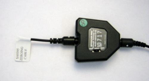
With the zeroing plug on the sensor, the reading should be zero. If your software displays a different value, usually plus or minus a few microvolts, then you should be able to correct this offset, from within the software, by using a zeroing function. Keep in mind that each sensor may have different offset values, and that the offset may change, particularly with temperature. Remember to remove the zeroing plug after adjusting the MyoScan-Pro sensor’s offset.
skin preparation
 Although it is possible to use the MyoScan-Pro sensor with dry electrodes and no skin preparation, doing so increases the chance that artifacts will distort the signal. As a general rule, skin preparation enhances signal quality, reduces artifacts and minimizes the need for post-recording artifact rejection.
At a minimum, make sure that before applying the EMG electrodes the skin surface is clean and dry by rubbing it with an alcohol pad. However, to significantly reduce artifacts, we recommend abrading the skin with an abrasive cream, such as NuPrep (10-30), to remove dead skin. If necessary, shave excess body hair.
sensor placement
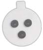
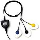
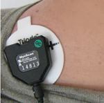 For best results, silver-silver chloride electrodes are recommended for electrical contact between skin and sensor. The single-use Triode electrode (T3402M) should be your first choice. It can be snapped directly on the sensor head, which makes it very easy to use and quick to position. The signal is then amplified right on the muscle site, which dramatically increases the SNR (Signal-to-Noise Ratio) and therefore limits pollution of the SEMG signal by surrounding electromagnetic fields and movement artifacts generated by wires being pulled.
The distance between the electrodes is also optimal (standard 2cm) for avoiding or limiting muscle crosstalk.
Conductive gel is recommended for optimal electrode-skin contact. The gel can be applied to the center (on the grey area only) before applying to the skin. Make sure the electrodes are placed firmly on the skin.
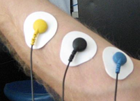 The UniGel electrodes (T3425) provide total freedom in term of placement. Their small size also allows placement on very tiny muscles (such as SCM). They are not attached together, which prevents them from moving on the skin when positioned on muscles with great deformation while contracting. These electrodes are pre-gelled and so do not require the addition of conductive gel, which reduces the time of preparation for this type of electrodes. An EMG extender cable (T8720M) must be connected between the electrodes and the sensor.
Technical Specifications
- Size : 37mm x 37mm x 12mm (1.45" x 1.45" x 0.45")
- Weight : 25g (0.5 oz)
- Input Impedance : > 10¹²Ω in parallel with 10pF
- Signal Input Range : 0 – 2000 uVRMS
- Sensitivity : < 0.1 uVRMS
- CMRR : > 130 dB
- Channel Bandwidth : 10 Hz-1 kHz
- Signal Output Range : ±2.0V (+ 2.8V if used with Sensor Isolator)
- Input / Output Gain : 0 – 400 uVRMS, 0 – 1600 uVRMS
- Supply Voltage : 7.26 V (±0.02 V)
- Current Consumption : < 1.5mA
- Accuracy : ±5%
Electrical Compatibility
The MyoScan-Pro sensor is designed to coexist with other Thought Technology bio potential sensors such as T9306 (or T9307) EKG sensor, T9305M EEG sensor, T7680 EEG-Z3 sensor, or SA9309M Skin Conductance sensor.
To ensure correct MyoScan sensor operation, if sensors from another manufacturer are in the same electrical circuit and connected to the same subject, their electrodes must function at a voltage within the specified operating bias range, 1.0 to 3.0 volts above sensor ground. To check whether another sensor is interfering with the MyoScan sensor operation, connect and disconnect the other sensor from the subject, and note whether this causes a change in the MyoScan-Pro sensor signal level, or whether connection of the other sensor appears to cause any signal artifacts in the EMG signal.
Interfacing with 3rd Party Data Acquisition Systems
Recommended Connectivity for Electrical Safety
To ensure electrical safety in the user setup, Thought Technology recommends the use of TT Sensor Isolator ST9405AM when interfacing patient connected sensor(s) to line powered equipment(s) or devices.
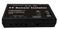 The TT Sensor Isolator ST9405AM is an interface device providing medical grade electrical isolation between the patient connected sensors and the acquisition system. It provides the equivalent of Two Means of Patient Protection under IEC 60601-1, and supplies battery power to the sensors. Using this device ensures Thought Technology sensors are safely interfaced to the analog inputs of line-powered systems such as computers with DAQ cards.
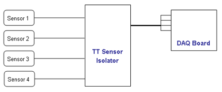
Note that this device isolates only between sensors and the DAQ interface, not between different sensor channels.
The TT Sensor Isolator can interface up to 4 sensors to a DAQ card. TT Sensor Isolator can be connected to the DAQ card in two ways:
- via two stereo jacks, or
- via a DB-15 connector; a BNC interface cable (SA9409BNC) or a pigtail cable (SA9409PGT) can be provided with the unit.
For more detailed information on the Sensor Isolator 4∞, consult the Thought Technology Science Division website or contact the sales department or your distributor.
Direct Connectivity for Electrically Isolated Systems
The following notes are provided for qualified users to directly interface Thought Technology sensors with external systems.
WARNING: If the sensor is interfaced to non-Thought Technology devices without the use of a TT Sensor Isolator SE9405AM, an elevated risk of electrical shock may be present. In particular, if a patient-connected sensor is connected to any line powered device(s) or equipment(s), it will be the responsibility of the qualified user to ensure the electrical safety in the setup and to ensure that the device or equipment provides sufficient isolation.
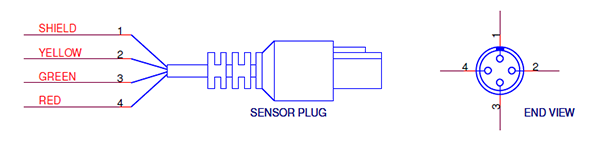
To interface with a sensor, a single sensor cable may be cut in half. Both sides can then be used to make custom interfacing cables by stripping the outer insulation of each required conductor. The sensor cable contains 4 color coded conductors. The table below shows the color coding and pin connector assignment.
| Pin | Color Code | Function | Note |
| 1 | metal (shield) | ground | Signal and power ground, connection required. |
| 2 | yellow | auxiliary (sensor ID) | No connection required. |
| 3 | green | signal | Sensor output signal |
| 4 | red | sensor power | Supply voltage, +7.26V referenced to ground. Note: sensor performance may be sensitive to supply voltage. |
Notes:
The nominal supply voltage for this sensor is 7.26V. The sensor can safely be used with a supply voltage of up to 9V. However, as the sensor is calibrated with a 7.26V supply voltage level, changes in gain and offset may be expected when operating at a different supply voltage level, changes in gain and offset may be expected when operating at a different supply voltage.
General Specifications and Recommendations
- Recommended minimum 16-bit ADC
- Input range:
- Connected using the product SE9405AM Sensor Isolator: 0-5V (unipolar) or ±5V
- Direct connect with AC coupled output and DC bias resistor: ±1.25V or ±2.5V
Simplified Transfer Function
| Switch setting | Output voltage from input | Input voltage from output |
| 400W, 400N | ||
| 1600W |  |
Vout: Output voltage (input to DAQ)
Vin: Input voltage (RMS EMG signal)
Notes:
The formula takes into account the 2.8 V item in Vout. the 2.8 V item is present if the TT Sensor Isolator used; it is absent (subtract it from Vout) if the EMG sensor is directly connected to a Data Acquisition card, and if a resistor is connected across its output (see section below).
Specification Summaries Of Supported Accessories / Hardware
Table below lists Thought Technology accessories for the MyoScan Pro.
| Accessory |
Product Number |
 |
T8720M EXTENDER CABLE 21in, 53cm |
Product Overview
The MyoScan-Pro line of sensors is differential amplifier of surface electromyography (sEMG). This means that whatever electrical activity is common to both sites is rejected, and what differs is amplified.
Surface EMG is a non-invasive measure of underlying muscle activity by detecting and amplifying tiny electrical impulses generated by muscle fibers when they contract.
The sensor detects and averages a complex addition of impulses from many muscle fibers within the recording area of the sensor, contracting at different moments and at different rates. The number of muscle fibers that are recruited, and the rate of firing (contraction) of each fiber, during any given contraction depends on the force required to perform the movement. Because of this, the intensity (amplitude) of the resulting electrical signal, under certain condition, is proportional to the strength of contraction.
For more information on SEMG and its applications, the following free ebooks are available for download:
|
|
| Basics of Surface Electromyography Applied to Psychophysiology |
The Basics of Surface Electromyography Applied to Physical Rehabilitation and Biomechanics |
OPERATING PRINCIPLE
The MyoScan-Pro sensor senses and amplifies EMG signal and then performs an analog root mean square (RMS) conversion on the signal. It results in a relatively slowly changing signal which follows the amplitude of the input EMG signal, and which can be sampled at a lower rate that what is required for raw EMG.
Before the RMS conversion, the SEMG signal is notched to remove power line frequencies which are present in many environments. MyoScan-Pro T9401M-60/SA9401M-60 notches at 60Hz and MyoScan-Pro T9401M-50/SA9401M-50 at 50Hz. The MyoScan-Pro sensor’s frequency response is from 20 to 500 Hz. It responds to SEMG signals up to 1600 micro-volts (μV) RMS. On the back of the sensor, there is a small switch with three positions: 400N, 1600W and 400W:
- In the 400W (wide bandwidth) position, the sensor will be sensitive to the full 20-500Hz bandwidth. SEMG signals recorded from upper body muscles may contain EKG interference from heart muscle. This is usually seen as a spike occurring at every heartbeat.
- This noise can be filtered out by moving the switch to the 400N (narrow bandwidth) position. In this position, the sensor will only be sensitive to frequencies between 100 and 200 Hz.
While the 400 (W and N) settings provide good resolution for most of the body’s muscles, the third position, 1600W is for monitoring larger muscle groups like thigh muscles, where the signal level may go above 400uV RMS. In this setting, the sensor responds up to a level of 1600uV RMS.
Zeroing
Since the MyoScan-Pro uses internal electronic circuitry to perform RMS conversion, small offsets are sometimes observed in the sensor reading. For that reason, it will occasionally be necessary to zero your MyoScan-Pro sensors. Zeroing is done by connecting the zeroing plug to the sensor box (plug it where the extender cable connects).
With the zeroing plug on the sensor, the reading should be zero. If your software displays a different value, usually plus or minus a few microvolts, then you should be able to correct this offset, from within the software, by using a zeroing function. Keep in mind that each sensor may have different offset values, and that the offset may change, particularly with temperature. Remember to remove the zeroing plug after adjusting the MyoScan-Pro sensor’s offset.
skin preparation
Although it is possible to use the MyoScan-Pro sensor with dry electrodes and no skin preparation, doing so increases the chance that artifacts will distort the signal. As a general rule, skin preparation enhances signal quality, reduces artifacts and minimizes the need for post-recording artifact rejection.
At a minimum, make sure that before applying the EMG electrodes the skin surface is clean and dry by rubbing it with an alcohol pad. However, to significantly reduce artifacts, we recommend abrading the skin with an abrasive cream, such as NuPrep (10-30), to remove dead skin. If necessary, shave excess body hair.
sensor placement
For best results, silver-silver chloride electrodes are recommended for electrical contact between skin and sensor. The single-use Triode electrode (T3402M) should be your first choice. It can be snapped directly on the sensor head, which makes it very easy to use and quick to position. The signal is then amplified right on the muscle site, which dramatically increases the SNR (Signal-to-Noise Ratio) and therefore limits pollution of the SEMG signal by surrounding electromagnetic fields and movement artifacts generated by wires being pulled.
The distance between the electrodes is also optimal (standard 2cm) for avoiding or limiting muscle crosstalk.
Conductive gel is recommended for optimal electrode-skin contact. The gel can be applied to the center (on the grey area only) before applying to the skin. Make sure the electrodes are placed firmly on the skin.
The UniGel electrodes (T3425) provide total freedom in term of placement. Their small size also allows placement on very tiny muscles (such as SCM). They are not attached together, which prevents them from moving on the skin when positioned on muscles with great deformation while contracting. These electrodes are pre-gelled and so do not require the addition of conductive gel, which reduces the time of preparation for this type of electrodes. An EMG extender cable (T8720M) must be connected between the electrodes and the sensor.
Technical Specifications
- Size : 37mm x 37mm x 12mm (1.45" x 1.45" x 0.45")
- Weight : 25g (0.5 oz)
- Input Impedance : > 10¹²Ω in parallel with 10pF
- Signal Input Range : 0 – 2000 uVRMS
- Sensitivity : < 0.1 uVRMS
- CMRR : > 130 dB
- Channel Bandwidth : 10 Hz-1 kHz
- Signal Output Range : ±2.0V (+ 2.8V if used with Sensor Isolator)
- Input / Output Gain : 0 – 400 uVRMS, 0 – 1600 uVRMS
- Supply Voltage : 7.26 V (±0.02 V)
- Current Consumption : < 1.5mA
- Accuracy : ±5%
Electrical Compatibility
The MyoScan-Pro sensor is designed to coexist with other Thought Technology bio potential sensors such as T9306 (or T9307) EKG sensor, T9305M EEG sensor, T7680 EEG-Z3 sensor, or SA9309M Skin Conductance sensor.
To ensure correct MyoScan sensor operation, if sensors from another manufacturer are in the same electrical circuit and connected to the same subject, their electrodes must function at a voltage within the specified operating bias range, 1.0 to 3.0 volts above sensor ground. To check whether another sensor is interfering with the MyoScan sensor operation, connect and disconnect the other sensor from the subject, and note whether this causes a change in the MyoScan-Pro sensor signal level, or whether connection of the other sensor appears to cause any signal artifacts in the EMG signal.
Interfacing with 3rd Party Data Acquisition Systems
Recommended Connectivity for Electrical Safety
To ensure electrical safety in the user setup, Thought Technology recommends the use of TT Sensor Isolator ST9405AM when interfacing patient connected sensor(s) to line powered equipment(s) or devices.
The TT Sensor Isolator ST9405AM is an interface device providing medical grade electrical isolation between the patient connected sensors and the acquisition system. It provides the equivalent of Two Means of Patient Protection under IEC 60601-1, and supplies battery power to the sensors. Using this device ensures Thought Technology sensors are safely interfaced to the analog inputs of line-powered systems such as computers with DAQ cards.
Note that this device isolates only between sensors and the DAQ interface, not between different sensor channels.
The TT Sensor Isolator can interface up to 4 sensors to a DAQ card. TT Sensor Isolator can be connected to the DAQ card in two ways:
- via two stereo jacks, or
- via a DB-15 connector; a BNC interface cable (SA9409BNC) or a pigtail cable (SA9409PGT) can be provided with the unit.
For more detailed information on the Sensor Isolator 4∞, consult the Thought Technology Science Division website or contact the sales department or your distributor.
Direct Connectivity for Electrically Isolated Systems
The following notes are provided for qualified users to directly interface Thought Technology sensors with external systems.
WARNING: If the sensor is interfaced to non-Thought Technology devices without the use of a TT Sensor Isolator SE9405AM, an elevated risk of electrical shock may be present. In particular, if a patient-connected sensor is connected to any line powered device(s) or equipment(s), it will be the responsibility of the qualified user to ensure the electrical safety in the setup and to ensure that the device or equipment provides sufficient isolation.
To interface with a sensor, a single sensor cable may be cut in half. Both sides can then be used to make custom interfacing cables by stripping the outer insulation of each required conductor. The sensor cable contains 4 color coded conductors. The table below shows the color coding and pin connector assignment.
| Pin | Color Code | Function | Note |
| 1 | metal (shield) | ground | Signal and power ground, connection required. |
| 2 | yellow | auxiliary (sensor ID) | No connection required. |
| 3 | green | signal | Sensor output signal |
| 4 | red | sensor power | Supply voltage, +7.26V referenced to ground. Note: sensor performance may be sensitive to supply voltage. |
Notes:
The nominal supply voltage for this sensor is 7.26V. The sensor can safely be used with a supply voltage of up to 9V. However, as the sensor is calibrated with a 7.26V supply voltage level, changes in gain and offset may be expected when operating at a different supply voltage level, changes in gain and offset may be expected when operating at a different supply voltage.
General Specifications and Recommendations
- Recommended minimum 16-bit ADC
- Input range:
- Connected using the product SE9405AM Sensor Isolator: 0-5V (unipolar) or ±5V
- Direct connect with AC coupled output and DC bias resistor: ±1.25V or ±2.5V
Simplified Transfer Function
| Switch setting | Output voltage from input | Input voltage from output |
| 400W, 400N | ||
| 1600W | |
Vout: Output voltage (input to DAQ)
Vin: Input voltage (RMS EMG signal)
Notes:
The formula takes into account the 2.8 V item in Vout. the 2.8 V item is present if the TT Sensor Isolator used; it is absent (subtract it from Vout) if the EMG sensor is directly connected to a Data Acquisition card, and if a resistor is connected across its output (see section below).
Specification Summaries Of Supported Accessories / Hardware
Table below lists Thought Technology accessories for the MyoScan Pro.
| Accessory |
Product Number |
|
T8720M EXTENDER CABLE 21in, 53cm |
Technical Specifications
| Size : 37mm x 37mm x 12mm (1.45" x 1.45" x 0.45") |
| Weight : 25g (0.5 oz) |
| Input Impedance : > 10¹²Ω in parallel with 10pF |
| Signal Input Range :0 – 2000 uVRMS |
| Sensitivity : < 0.1 uVRMS |
| CMRR : > 130 dB |
| Channel Bandwidth :10 Hz-1 kHz |
| Signal Output Range :±2.0V (+ 2.8V if used with Sensor Isolator) |
| Input / Output Gain :0 – 400 uVRMS, 0 – 1600 uVRMS |
| Supply Voltage :7.26 V (±0.02 V) |
| Current Consumption : < 1.5mA |
| Accuracy :±5% |
More Products to Consider
 TT Infra Sensor
Table of Contents