 & DUAL-INCLINOTRAC (T7655)")
Inclinotrac & Dual-Inclinotrac
Model: T7650 / T7655
- Single InclinoTrac is an inclinometer that measures the inclination angle relative to the ground. It uses solid-state micro-machined sensors and microprocessor technology to provide rapid settling and high resolution (0.1°) and accuracy (1.0°).
- Dual-InclinoTrac is a dual version that measures relative angle (between back and head, for instance). Ideal choice for Range of Motion assessment.
Product Overview
InclinoTrac is a single inclinometer that measures the inclination angle relative to the ground.
Dual-InclinoTrac is a dual inclinometer that measures relative angle (between back and head, for instance).
InclinoTrac and Dual-InclinoTrac use solid-state micro-machined sensors and microprocessor technology to provide rapid settling and high resolution (0.1°) and accuracy (1.0°). They are the ideal choice for Range of Motion (ROM) assessment.
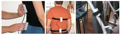
They can be used in various ways: simply put on the examinee, or attached with straps on either the examinee or the workout machine.
Operating Principles
This section gives recommendations for ensuring accuracy and consistency of measurement.
Being familiar with the tools
The single inclinometer is called InclinoTrac.
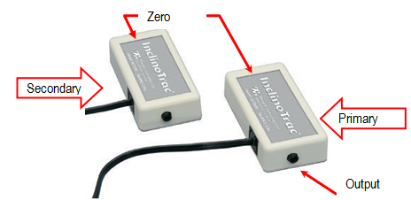
The dual inclinometer is called Dual-InclinoTrac (see picture below), and consists of two InclinoTracs connected together.
Dual-InclinoTrac
The plug at one end is used to connect the inclinometer to the DAQ. The Zero button at other end is used to mark the neutral zero.
Two devices are connected together by a cable. The connector is on the side of the device (see picture above). The inclinometer connected to the DAQ is then called the “primary”. The other one is called the “secondary”.
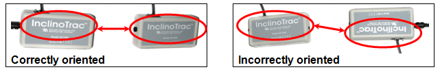
The dual inclinometer outputs the angle between the primary and secondary devices. The primary and secondary must be oriented so that the “InclinoTrac” labels face the same way. Either zero button can be used to mark the neutral position.
Calibrating the Inclinometer (zeroing)
Make sure your inclinometer is properly calibrated. The inclinometer must be recalibrated if you press the zero button and the screen does not display the value "0" (zero).
Straps or No Straps?
That is the question. Straps were designed to be used for dynamic ROM assessment, ROM therapy and for the static ROM assessment of the extremities. Holding manually the inclinometers is strongly recommended in the case of static spine assessment. However, straps may be used to assist you in holding the inclinometers (on the head, for instance) and avoid them to slip, or when you assist the examinee in a passive motion.
If you manually handle the inclinometers, make sure you apply a constant pressure throughout the range of motion.
If you use a strap to attach the inclinometer, make sure that the strap is secured and cannot move against the body part during the motion.
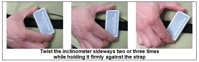
Also check that the inclinometer is firmly fixed to the strap. To do this, press it against the strap and twist it sideways two or three times, so that the hooks and loops are thoroughly enmeshed.
This will ensure the inclinometer keeps the same orientation against the body part in motion and does not slip from its original position.
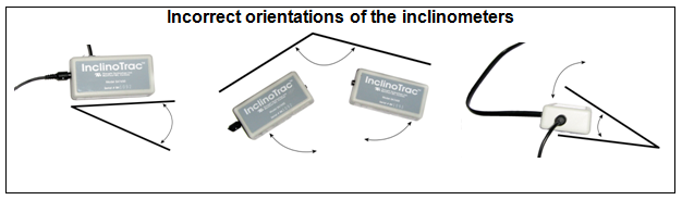
Proper orientation
The guide suggests positions of the inclinometers for each range of motion. You may find that different positions are more convenient for you or the examinee.
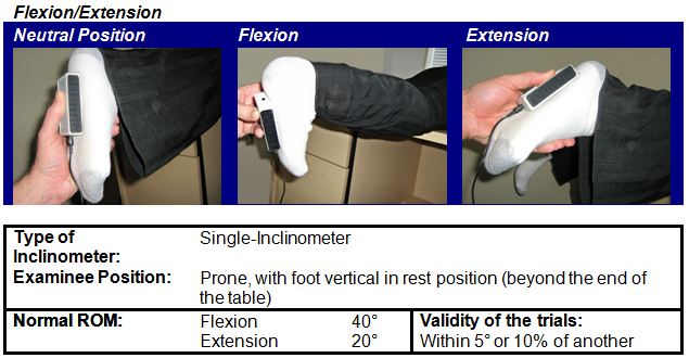
However, you have to pay attention to the orientation of the inclinometers. The first motion of the two (for instance, “flexion” in “flexion/extension”) must give a positive angle and the second motion (“extension”) a negative angle. The system will rectify the angles in the report according to this rule.
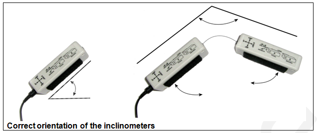
Always keep the side with the inclinometer plug within 45° of the vertical plane and parallel to the plane of motion.
Sensor Placement
This section proposes typical sensor placements with AMA normative data (Andersson Gunnar B. J. & Cocchiarella Linda. (2007). Guides to the Evaluation of Permanent Impairment, 6th Edition. American Medical Association).
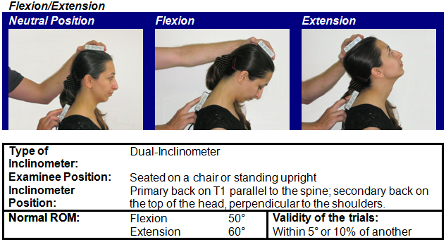
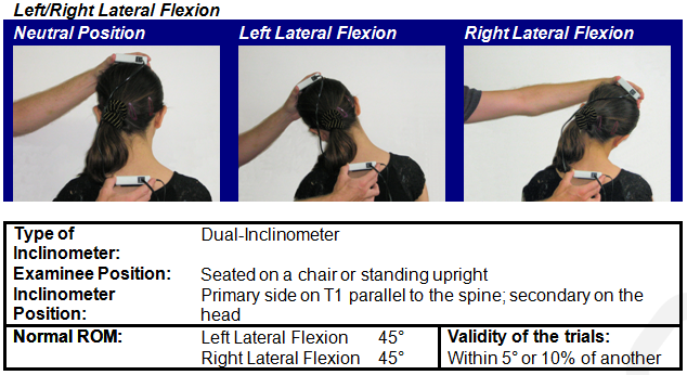
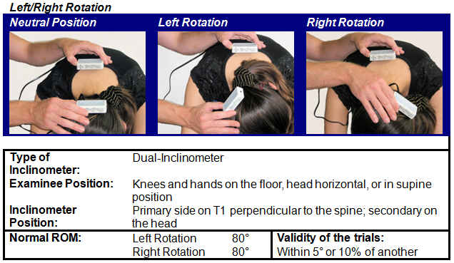
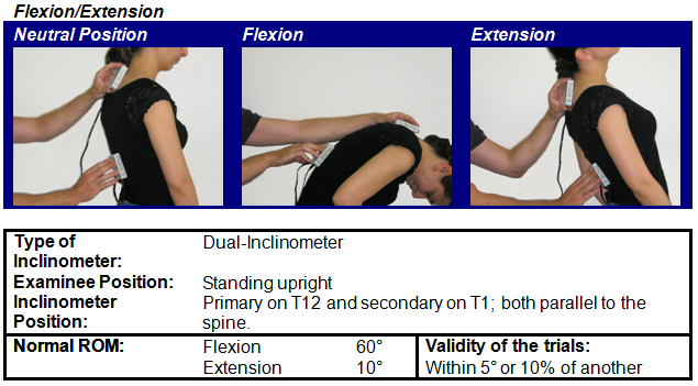
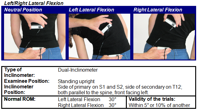
SROM – Cervical Spine
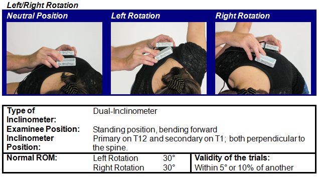
SROM – Thoracic Spine
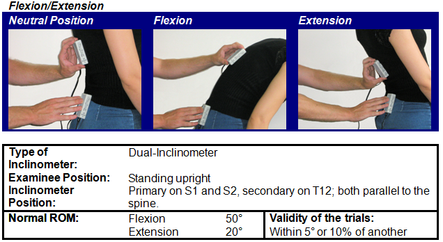
SROM – Lumbar Spine
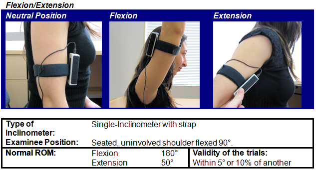
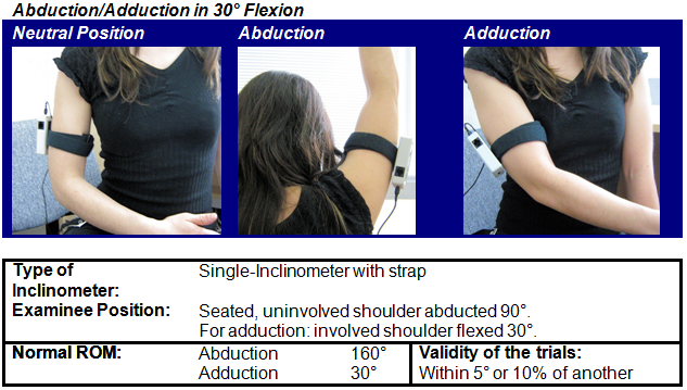
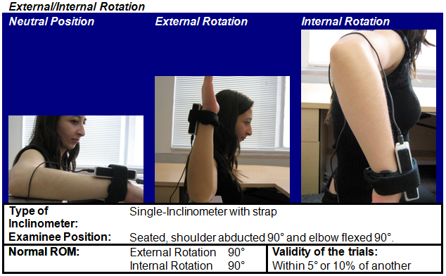
SROM – Shoulder
SROM – Elbow
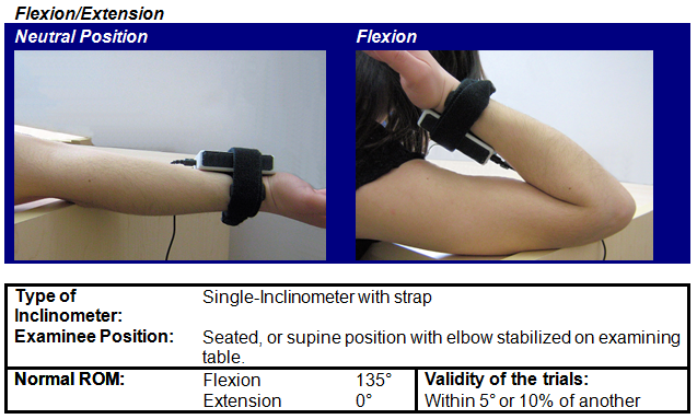
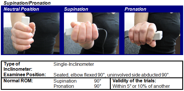
SROM – Forearm
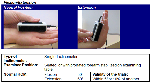
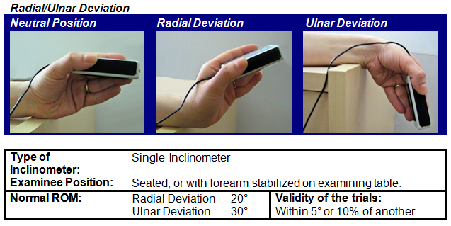
SROM – Wrist
SROM – Hip
SROM – Knee
SROM – Ankle
Technical Specifications
- Dimensions : 32mm x 18mm x 71mm
- Weight (approx.) : 26g
- Range : ± 180°
- Accuracy (operated in vertically-oriented plane)
≤ 2.0° (dual mode, angle difference) : ≤ 1.0° (standalone mode) - Output gain : 4.44mV / degree inclination
- Output voltage span : 2.200 ± 0.8V
- Power supply : 7.26V
- Current consumption, maximum : 9.5 mA (standalone mode)
19.0 mA (dual mode) - Link cable : RJ-11, 2 pairs, reversed
(this is not a standard telephone cable)
Interfacing with 3rd Party Data Acquisition Systems
Recommended Connectivity for Electrical Safety
Thought Technology recommends the use of TT Sensor Isolator ST9405AM when interfacing patient connected sensor(s) to line powered equipment(s) or devices.
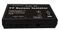 The TT Sensor Isolator ST9405AM is an interface device providing medical grade electrical isolation between the patient connected sensors and the acquisition system. It provides the equivalent of Two Means of Patient Protection under IEC 60601-1, and supplies battery power to the sensors. Using this device ensures Thought Technology sensors are safely interfaced to the analog inputs of line-powered systems such as computers with DAQ cards.
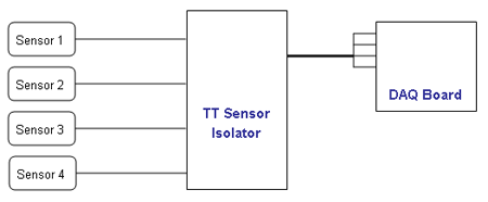
Note that this device isolates only between sensors and the DAQ interface, not between different sensor channels.
The TT Sensor Isolator can interface up to 4 sensors to a DAQ card. TT Sensor Isolator can be connected to the DAQ card in two ways:
- via two stereo jacks, or
- via a DB-15 connector; a BNC interface cable (SA9409BNC) or a pigtail cable (SA9409PGT) can be provided with the unit.
For more detailed information on the Sensor Isolator 4∞, consult the Thought Technology Science Division website or contact the sales department or your distributor.
Division website or contact the sales department or your distributor.
Direct Connectivity for Electrically Isolated Systems
The following notes are provided for qualified users to directly interface Thought Technology sensors with external systems.
WARNING: If the sensor is interfaced to non-Thought Technology devices without the use of a TT Sensor Isolator SE9405AM, an elevated risk of electrical shock may be present. In particular, if a patient-connected sensor is connected to any line powered device(s) or equipment(s), it will be the responsibility of the qualified user to ensure the electrical safety in the setup and to ensure that the device or equipment provides sufficient isolation.
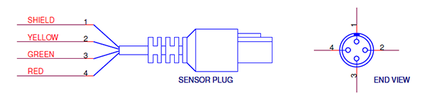
To interface with a sensor, a single sensor cable may be cut in half. Both sides can then be used to make custom interfacing cables by stripping the outer insulation of each required conductor. The sensor cable contains 4 color coded conductors. The table below shows the color coding and pin connector assignment.
| Pin | Color Code | Function | Note |
| 1 | metal (shield) | ground | Signal and power ground, connection required. |
| 2 | yellow | auxiliary (sensor ID) | No connection required. |
| 3 | green | signal | Sensor output signal |
| 4 | red | sensor power | Supply voltage, +7.26V referenced to ground. Note: sensor performance may be sensitive to supply voltage. |
Notes:
1. The nominal supply voltage for this sensor is 7.26V. The sensor can safely be used with a supply voltage of up to 9V.
Recommended Specifications for DAQ Hardware
- Recommended resolution of 0.15mV (16-bit ADC over 10V span) or better
- Minimum input range:
- If connected via SE9405AM Sensor Isolator, choose 0-5V (unipolar) or ±5V (bipolar).
- If directly connected to DAQ, choose ±5V (bipolar).
Simplified Transfer Function
![]() Conversion of voltage [V] to output angle in degrees.
Conversion of voltage [V] to output angle in degrees.
Product Overview
InclinoTrac is a single inclinometer that measures the inclination angle relative to the ground.
Dual-InclinoTrac is a dual inclinometer that measures relative angle (between back and head, for instance).
InclinoTrac and Dual-InclinoTrac use solid-state micro-machined sensors and microprocessor technology to provide rapid settling and high resolution (0.1°) and accuracy (1.0°). They are the ideal choice for Range of Motion (ROM) assessment.
They can be used in various ways: simply put on the examinee, or attached with straps on either the examinee or the workout machine.
Operating Principles
This section gives recommendations for ensuring accuracy and consistency of measurement.
Being familiar with the tools
The single inclinometer is called InclinoTrac.
The dual inclinometer is called Dual-InclinoTrac (see picture below), and consists of two InclinoTracs connected together.
Dual-InclinoTrac
The plug at one end is used to connect the inclinometer to the DAQ. The Zero button at other end is used to mark the neutral zero.
Two devices are connected together by a cable. The connector is on the side of the device (see picture above). The inclinometer connected to the DAQ is then called the “primary”. The other one is called the “secondary”.
The dual inclinometer outputs the angle between the primary and secondary devices. The primary and secondary must be oriented so that the “InclinoTrac” labels face the same way. Either zero button can be used to mark the neutral position.
Calibrating the Inclinometer (zeroing)
Make sure your inclinometer is properly calibrated. The inclinometer must be recalibrated if you press the zero button and the screen does not display the value "0" (zero).
Straps or No Straps?
That is the question. Straps were designed to be used for dynamic ROM assessment, ROM therapy and for the static ROM assessment of the extremities. Holding manually the inclinometers is strongly recommended in the case of static spine assessment. However, straps may be used to assist you in holding the inclinometers (on the head, for instance) and avoid them to slip, or when you assist the examinee in a passive motion.
If you manually handle the inclinometers, make sure you apply a constant pressure throughout the range of motion.
If you use a strap to attach the inclinometer, make sure that the strap is secured and cannot move against the body part during the motion.
Also check that the inclinometer is firmly fixed to the strap. To do this, press it against the strap and twist it sideways two or three times, so that the hooks and loops are thoroughly enmeshed.
This will ensure the inclinometer keeps the same orientation against the body part in motion and does not slip from its original position.
Proper orientation
The guide suggests positions of the inclinometers for each range of motion. You may find that different positions are more convenient for you or the examinee.
However, you have to pay attention to the orientation of the inclinometers. The first motion of the two (for instance, “flexion” in “flexion/extension”) must give a positive angle and the second motion (“extension”) a negative angle. The system will rectify the angles in the report according to this rule.
Always keep the side with the inclinometer plug within 45° of the vertical plane and parallel to the plane of motion.
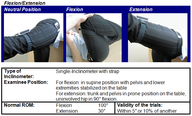
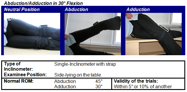
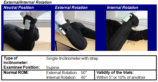
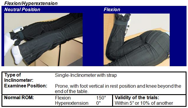
Sensor Placement
This section proposes typical sensor placements with AMA normative data (Andersson Gunnar B. J. & Cocchiarella Linda. (2007). Guides to the Evaluation of Permanent Impairment, 6th Edition. American Medical Association).
SROM – Cervical Spine
SROM – Thoracic Spine
SROM – Lumbar Spine
SROM – Shoulder
SROM – Elbow
SROM – Forearm
SROM – Wrist
SROM – Hip
SROM – Knee
SROM – Ankle
Technical Specifications
- Dimensions : 32mm x 18mm x 71mm
- Weight (approx.) : 26g
- Range : ± 180°
- Accuracy (operated in vertically-oriented plane)
≤ 2.0° (dual mode, angle difference) : ≤ 1.0° (standalone mode) - Output gain : 4.44mV / degree inclination
- Output voltage span : 2.200 ± 0.8V
- Power supply : 7.26V
- Current consumption, maximum : 9.5 mA (standalone mode)
19.0 mA (dual mode) - Link cable : RJ-11, 2 pairs, reversed
(this is not a standard telephone cable)
Interfacing with 3rd Party Data Acquisition Systems
Recommended Connectivity for Electrical Safety
Thought Technology recommends the use of TT Sensor Isolator ST9405AM when interfacing patient connected sensor(s) to line powered equipment(s) or devices.
The TT Sensor Isolator ST9405AM is an interface device providing medical grade electrical isolation between the patient connected sensors and the acquisition system. It provides the equivalent of Two Means of Patient Protection under IEC 60601-1, and supplies battery power to the sensors. Using this device ensures Thought Technology sensors are safely interfaced to the analog inputs of line-powered systems such as computers with DAQ cards.
Note that this device isolates only between sensors and the DAQ interface, not between different sensor channels.
The TT Sensor Isolator can interface up to 4 sensors to a DAQ card. TT Sensor Isolator can be connected to the DAQ card in two ways:
- via two stereo jacks, or
- via a DB-15 connector; a BNC interface cable (SA9409BNC) or a pigtail cable (SA9409PGT) can be provided with the unit.
For more detailed information on the Sensor Isolator 4∞, consult the Thought Technology Science Division website or contact the sales department or your distributor.
Division website or contact the sales department or your distributor.
Direct Connectivity for Electrically Isolated Systems
The following notes are provided for qualified users to directly interface Thought Technology sensors with external systems.
WARNING: If the sensor is interfaced to non-Thought Technology devices without the use of a TT Sensor Isolator SE9405AM, an elevated risk of electrical shock may be present. In particular, if a patient-connected sensor is connected to any line powered device(s) or equipment(s), it will be the responsibility of the qualified user to ensure the electrical safety in the setup and to ensure that the device or equipment provides sufficient isolation.
To interface with a sensor, a single sensor cable may be cut in half. Both sides can then be used to make custom interfacing cables by stripping the outer insulation of each required conductor. The sensor cable contains 4 color coded conductors. The table below shows the color coding and pin connector assignment.
| Pin | Color Code | Function | Note |
| 1 | metal (shield) | ground | Signal and power ground, connection required. |
| 2 | yellow | auxiliary (sensor ID) | No connection required. |
| 3 | green | signal | Sensor output signal |
| 4 | red | sensor power | Supply voltage, +7.26V referenced to ground. Note: sensor performance may be sensitive to supply voltage. |
Notes:
1. The nominal supply voltage for this sensor is 7.26V. The sensor can safely be used with a supply voltage of up to 9V.
Recommended Specifications for DAQ Hardware
- Recommended resolution of 0.15mV (16-bit ADC over 10V span) or better
- Minimum input range:
- If connected via SE9405AM Sensor Isolator, choose 0-5V (unipolar) or ±5V (bipolar).
- If directly connected to DAQ, choose ±5V (bipolar).
Simplified Transfer Function
![]() Conversion of voltage [V] to output angle in degrees.
Conversion of voltage [V] to output angle in degrees.
Technical Specifications
| Dimensions :32mm x 18mm x 71mm |
| Weight (approx.) :26g |
| Range :± 180° |
| Accuracy (operated in vertically-oriented plane):≤ 2.0° (dual mode, angle difference) : ≤ 1.0° (standalone mode) |
| Output gain :4.44mV / degree inclination |
| Output voltage span :2.200 ± 0.8V |
| Power supply :7.26V |
| Current consumption, maximum : 9.5 mA (standalone mode) 19.0 mA (dual mode) |
| Link cable : RJ-11, 2 pairs, reversed (this is not a standard telephone cable) |
More Products to Consider
 TT Infra Sensor
Table of Contents
Suggested References