
EKG Sensor
Model: T9306M / T9307M
- EKG is a pre-amplified electrocardiograph sensor, for directly measuring heart electrical activity.
- Connects to the body via extender cables for single channel hook up.
Product Overview
The EKG sensor is an electrocardiograph sensor or pre-amplifier, for directly measuring the heart’s electrical activity. It amplifies the small electrical voltage that is generated by the heart muscle when it contracts.
EKG is similar to EMG (electromyography) which records signals from skeletal muscles, but with a different waveform from EMG. EKG signals are usually measured in microvolts (μV) or millivolts (mV).
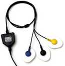 T9306M EKG sensor package includes the SA9306 EKG sensor and the SA8710M extender cable.
 T9307M EKG sensor package includes the SA9306 EKG sensor, and the SA9325 wrist straps. EKG wrist straps provide fast, convenient placement of electrodes for measuring EKG from the wrists. Non-latex medical straps are easy to apply, comfortable, and washable; and electrodes are replaceable.
For more information on EKG and its specific application of Heart Rate Variability (HRV), the following free ebook is available for download:
 |
| Basics of Surface Electromyography Applied to Psychophysiology |
skin preparation
 Although it is possible to use the EKG sensor with dry electrodes and no skin preparation, doing so increases the chance that artifacts will distort the signal and cause false heartbeat detection and heart rate calculation errors. As a general rule, skin preparation enhances signal quality, reduces artifacts and minimizes the need for post-recording artifact rejection.
At a minimum, make sure that before applying the EKG electrodes the skin surface is clean and dry by rubbing it with an alcohol pad. However, to significantly reduce artifacts, we recommend abrading the skin with an abrasive cream, such as NuPrep (10-30), to remove dead skin. If necessary, shave excess body hair.
![]() Conductive gel is recommended for optimal electrode-skin contact. Pre-gelled (UniGel) electrodes are easiest, but if using dry electrodes, conductive paste or gel can be applied to the center (on the grey area only) before applying to the skin. Make sure the electrodes are placed firmly on the skin and that there is good contact between skin and electrode.
Conductive gel is recommended for optimal electrode-skin contact. Pre-gelled (UniGel) electrodes are easiest, but if using dry electrodes, conductive paste or gel can be applied to the center (on the grey area only) before applying to the skin. Make sure the electrodes are placed firmly on the skin and that there is good contact between skin and electrode.
sensor placement
 For best results, silver-silver chloride electrodes are recommended for electrical contact between skin and sensor. To get a good signal, a widely spaced electrode placement is recommended, usually on the chest or on the forearms. This requires an electrode extender cable to connect the electrodes to the sensor. To further improve signal quality, we recommend pre-gelled electrodes such as Thought Technology UniGel (T3425M).
NOTE: Triode electrodes (T3402M) should not be used because its triangular configuration is not appropriate for detecting EKG signals.
 Chest Placement:
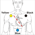
Ideal electrode placement for detecting EKG is a triangular configuration on the chest as illustrated, where yellow and blue electrodes are placed parallel to the heart's main axis. That is, Yellow and Black electrodes should be placed over the right and left coracoid processes, respectively, and the Blue electrode over the xiphoid process.
Abdominal Placement: When clients are uncomfortable exposing their chest area, an abdominal placement is an acceptable alternative. Place the Yellow electrode below the ribs on the right, and the Blue electrode at the same level on the left. The black electrode can go anywhere, but a good location is the upper sternum area.
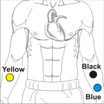 Arm Placement: An even easier electrode placement uses the forearms as illustrated. The Yellow electrode is placed on the right arm, with the other two on the left. Ideally, an area with little or no hair is preferred. Arm placement is more susceptible to artifacts, particularly from arm and chest muscle activity.
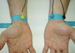
Wrist placement: The forearm electrode placement requires the use of an extender cable with longer leads like the one that is sold with the EKG Wrist straps (SA9325). The wrist straps provide the easiest placement method for EKG signal detection. However it is also more susceptible to movements and EMG artifacts and requires more advanced signal processing.
Technical Specifications
- Size : 37mm x 37mm x 12mm (1.45" x 1.45" x 0.45")
- Weight : 25g (0.5 oz)
- Input Impedance : > 10¹²Ω in parallel with 10pF
- Operating Input Bias : ~ 1.0 to 2.0 V above sensor ground
- Signal Input Range : ± 40 mV
- Channel Bandwidth : 0.05 Hz - 1 kHz
- Signal Output Range : ± 2.0 V (+ 2.8 V if used with Sensor Isolator)
- Input / Output Gain : 50
- Supply Voltage : 7.26 V (±0.05 V)
- Current Consumption : < 1.5 mA
- Accuracy : ±5%
Electrical Compatibility
The EKG sensor is designed to coexist with other Thought Technology bio potential sensors such as T9305 EEG sensor, T7680 EEG-Z3 sensor, T9303M MyoScan sensor, or SA9309M Skin Conductance sensor.
To ensure correct EKG sensor operation, if sensors from another manufacturer are in the same electrical circuit and connected to the same subject, their electrodes must function at a voltage within the specified operating bias range, 1.0 to 3.0 volts above sensor ground. To check whether another sensor is interfering with the EKG sensor operation, connect and disconnect the other sensor from the subject, and note whether this causes a change in the EKG sensor signal level, or whether connection of the other sensor appears to cause any signal artifacts in the EKG signal.
Interfacing with 3rd Party Data Acquisition Systems
Recommended Connectivity for Electrical Safety
To ensure electrical safety in the user setup, Thought Technology recommends the use of TT Sensor Isolator ST9405AM when interfacing patient connected sensor(s) to line powered equipment(s) or devices.
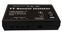 The TT Sensor Isolator ST9405AM is an interface device providing medical grade electrical isolation between the patient connected sensors and the acquisition system. It provides the equivalent of Two Means of Patient Protection under IEC 60601-1, and supplies battery power to the sensors. Using this device ensures Thought Technology sensors are safely interfaced to the analog inputs of line-powered systems such as computers with DAQ cards.
Note that this device isolates only between sensors and the DAQ interface, not between different sensor channels.
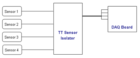
The TT Sensor Isolator can interface up to 4 sensors to a DAQ card. TT Sensor Isolator can be connected to the DAQ card in two ways:
- via two stereo jacks, or
- via a DB-15 connector; a BNC interface cable (SA9409BNC) or a pigtail cable (SA9409PGT) can be provided with the unit.
For more detailed information on the Sensor Isolator 4∞, consult the Thought Technology Science Division website or contact the sales department or your distributor.
Division website or contact the sales department or your distributor.
Direct Connectivity for Electrically Isolated Systems
The following notes are provided for qualified users to directly interface Thought Technology sensors with external systems.
WARNING: If the sensor is interfaced to non-Thought Technology devices without the use of a TT Sensor Isolator SE9405AM, an elevated risk of electrical shock may be present. In particular, if a patient-connected sensor is connected to any line powered device(s) or equipment(s), it will be the responsibility of the qualified user to ensure the electrical safety in the setup and to ensure that the device or equipment provides sufficient isolation.
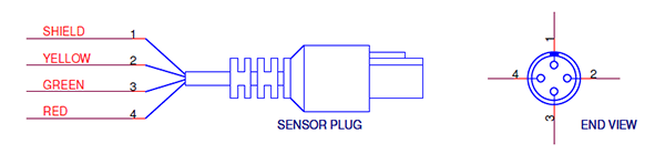
To interface with a sensor, a single sensor cable may be cut in half. Both sides can then be used to make custom interfacing cables by stripping the outer insulation of each required conductor. The sensor cable contains 4 color coded conductors. The table below shows the color coding and pin connector assignment.
| Pin | Color Code | Function | Note |
| 1 | metal (shield) | ground | Signal and power ground, connection required. |
| 2 | yellow | auxiliary (sensor ID) | No connection required. |
| 3 | green | signal | Sensor output signal |
| 4 | red | sensor power | Supply voltage, +7.26V referenced to ground. Note: sensor performance may be sensitive to supply voltage. |
Notes:
1. The nominal supply voltage for this sensor is 7.26V. The sensor can safely be used with a supply voltage of up to 9V. However, as the sensor is calibrated with a 7.26V supply voltage level, changes in gain and offset may be expected when operating at a different supply voltage level, changes in gain and offset may be expected when operating at a different supply voltage.
2. The output of the EKG sensor is AC (capacitive) coupled. Therefore, in order to set the DC level of the signal when connected to a DAQ system, it is usually necessary to connect a DC bias resistor between the signal (pin 3, green wire) and ground(pin 1, shield wire). A typical value for this resistor is 2.2 Megohms.
If no resistor is connected, the DC signal level may be unstable, and may drift upward or downward and saturate the DAQ input. This condition will result in an unusable signal but will not typically cause any equipment damage.
General Specifications and Recommendations
- Recommended minimum 16-bit ADC
- Input range:
- Connected using the product SE9405AM Sensor Isolator: 0-5V (unipolar) or ±5V
- Direct connect with AC coupled output and DC bias resistor: ±1.25V or ±2.5V
Simplified Transfer Function
![]() Output voltage (input to DAQ) from input voltage (EKG signal)
Output voltage (input to DAQ) from input voltage (EKG signal)
 Input voltage (EKG signal) from input voltage (input to DAQ)
Notes:
- The high pass effect of the sensor’s AC is not shown in the Transfer Function. The function is accurate for frequency components within the specified bandwidth, and should adequately represent the scaling of an EKG signal.
- The 2.8 V item is present if the TT Sensor Isolator used; it is absent if the EKG sensor is directly connected to a Data Acquisition card, and if a resistor is connected across its output (see section below).
Specification Summaries Of Supported Accessories / Hardware
Table below lists Thought Technology accessories for the EEG Sensor.
| Accessory |
Product Number |
|
SA8715 EKG EXTENDER CABLE for wrist strap 40in, 102cm 30 |
|
Wrist Strap kit (SA9325) |
|
T3425 – UniGel electrodes (single use): |
Product Overview
The EKG sensor is an electrocardiograph sensor or pre-amplifier, for directly measuring the heart’s electrical activity. It amplifies the small electrical voltage that is generated by the heart muscle when it contracts.
EKG is similar to EMG (electromyography) which records signals from skeletal muscles, but with a different waveform from EMG. EKG signals are usually measured in microvolts (μV) or millivolts (mV).
T9306M EKG sensor package includes the SA9306 EKG sensor and the SA8710M extender cable.
T9307M EKG sensor package includes the SA9306 EKG sensor, and the SA9325 wrist straps. EKG wrist straps provide fast, convenient placement of electrodes for measuring EKG from the wrists. Non-latex medical straps are easy to apply, comfortable, and washable; and electrodes are replaceable.
For more information on EKG and its specific application of Heart Rate Variability (HRV), the following free ebook is available for download:
|
| Basics of Surface Electromyography Applied to Psychophysiology |
skin preparation
Although it is possible to use the EKG sensor with dry electrodes and no skin preparation, doing so increases the chance that artifacts will distort the signal and cause false heartbeat detection and heart rate calculation errors. As a general rule, skin preparation enhances signal quality, reduces artifacts and minimizes the need for post-recording artifact rejection.
At a minimum, make sure that before applying the EKG electrodes the skin surface is clean and dry by rubbing it with an alcohol pad. However, to significantly reduce artifacts, we recommend abrading the skin with an abrasive cream, such as NuPrep (10-30), to remove dead skin. If necessary, shave excess body hair.
![]() Conductive gel is recommended for optimal electrode-skin contact. Pre-gelled (UniGel) electrodes are easiest, but if using dry electrodes, conductive paste or gel can be applied to the center (on the grey area only) before applying to the skin. Make sure the electrodes are placed firmly on the skin and that there is good contact between skin and electrode.
Conductive gel is recommended for optimal electrode-skin contact. Pre-gelled (UniGel) electrodes are easiest, but if using dry electrodes, conductive paste or gel can be applied to the center (on the grey area only) before applying to the skin. Make sure the electrodes are placed firmly on the skin and that there is good contact between skin and electrode.
sensor placement
For best results, silver-silver chloride electrodes are recommended for electrical contact between skin and sensor. To get a good signal, a widely spaced electrode placement is recommended, usually on the chest or on the forearms. This requires an electrode extender cable to connect the electrodes to the sensor. To further improve signal quality, we recommend pre-gelled electrodes such as Thought Technology UniGel (T3425M).
NOTE: Triode electrodes (T3402M) should not be used because its triangular configuration is not appropriate for detecting EKG signals.
Chest Placement:
Ideal electrode placement for detecting EKG is a triangular configuration on the chest as illustrated, where yellow and blue electrodes are placed parallel to the heart's main axis. That is, Yellow and Black electrodes should be placed over the right and left coracoid processes, respectively, and the Blue electrode over the xiphoid process.
Abdominal Placement: When clients are uncomfortable exposing their chest area, an abdominal placement is an acceptable alternative. Place the Yellow electrode below the ribs on the right, and the Blue electrode at the same level on the left. The black electrode can go anywhere, but a good location is the upper sternum area.
Arm Placement: An even easier electrode placement uses the forearms as illustrated. The Yellow electrode is placed on the right arm, with the other two on the left. Ideally, an area with little or no hair is preferred. Arm placement is more susceptible to artifacts, particularly from arm and chest muscle activity.
Wrist placement: The forearm electrode placement requires the use of an extender cable with longer leads like the one that is sold with the EKG Wrist straps (SA9325). The wrist straps provide the easiest placement method for EKG signal detection. However it is also more susceptible to movements and EMG artifacts and requires more advanced signal processing.
Technical Specifications
- Size : 37mm x 37mm x 12mm (1.45" x 1.45" x 0.45")
- Weight : 25g (0.5 oz)
- Input Impedance : > 10¹²Ω in parallel with 10pF
- Operating Input Bias : ~ 1.0 to 2.0 V above sensor ground
- Signal Input Range : ± 40 mV
- Channel Bandwidth : 0.05 Hz - 1 kHz
- Signal Output Range : ± 2.0 V (+ 2.8 V if used with Sensor Isolator)
- Input / Output Gain : 50
- Supply Voltage : 7.26 V (±0.05 V)
- Current Consumption : < 1.5 mA
- Accuracy : ±5%
Electrical Compatibility
The EKG sensor is designed to coexist with other Thought Technology bio potential sensors such as T9305 EEG sensor, T7680 EEG-Z3 sensor, T9303M MyoScan sensor, or SA9309M Skin Conductance sensor.
To ensure correct EKG sensor operation, if sensors from another manufacturer are in the same electrical circuit and connected to the same subject, their electrodes must function at a voltage within the specified operating bias range, 1.0 to 3.0 volts above sensor ground. To check whether another sensor is interfering with the EKG sensor operation, connect and disconnect the other sensor from the subject, and note whether this causes a change in the EKG sensor signal level, or whether connection of the other sensor appears to cause any signal artifacts in the EKG signal.
Interfacing with 3rd Party Data Acquisition Systems
Recommended Connectivity for Electrical Safety
To ensure electrical safety in the user setup, Thought Technology recommends the use of TT Sensor Isolator ST9405AM when interfacing patient connected sensor(s) to line powered equipment(s) or devices.
The TT Sensor Isolator ST9405AM is an interface device providing medical grade electrical isolation between the patient connected sensors and the acquisition system. It provides the equivalent of Two Means of Patient Protection under IEC 60601-1, and supplies battery power to the sensors. Using this device ensures Thought Technology sensors are safely interfaced to the analog inputs of line-powered systems such as computers with DAQ cards.
Note that this device isolates only between sensors and the DAQ interface, not between different sensor channels.
The TT Sensor Isolator can interface up to 4 sensors to a DAQ card. TT Sensor Isolator can be connected to the DAQ card in two ways:
- via two stereo jacks, or
- via a DB-15 connector; a BNC interface cable (SA9409BNC) or a pigtail cable (SA9409PGT) can be provided with the unit.
For more detailed information on the Sensor Isolator 4∞, consult the Thought Technology Science Division website or contact the sales department or your distributor.
Division website or contact the sales department or your distributor.
Direct Connectivity for Electrically Isolated Systems
The following notes are provided for qualified users to directly interface Thought Technology sensors with external systems.
WARNING: If the sensor is interfaced to non-Thought Technology devices without the use of a TT Sensor Isolator SE9405AM, an elevated risk of electrical shock may be present. In particular, if a patient-connected sensor is connected to any line powered device(s) or equipment(s), it will be the responsibility of the qualified user to ensure the electrical safety in the setup and to ensure that the device or equipment provides sufficient isolation.
To interface with a sensor, a single sensor cable may be cut in half. Both sides can then be used to make custom interfacing cables by stripping the outer insulation of each required conductor. The sensor cable contains 4 color coded conductors. The table below shows the color coding and pin connector assignment.
| Pin | Color Code | Function | Note |
| 1 | metal (shield) | ground | Signal and power ground, connection required. |
| 2 | yellow | auxiliary (sensor ID) | No connection required. |
| 3 | green | signal | Sensor output signal |
| 4 | red | sensor power | Supply voltage, +7.26V referenced to ground. Note: sensor performance may be sensitive to supply voltage. |
Notes:
1. The nominal supply voltage for this sensor is 7.26V. The sensor can safely be used with a supply voltage of up to 9V. However, as the sensor is calibrated with a 7.26V supply voltage level, changes in gain and offset may be expected when operating at a different supply voltage level, changes in gain and offset may be expected when operating at a different supply voltage.
2. The output of the EKG sensor is AC (capacitive) coupled. Therefore, in order to set the DC level of the signal when connected to a DAQ system, it is usually necessary to connect a DC bias resistor between the signal (pin 3, green wire) and ground(pin 1, shield wire). A typical value for this resistor is 2.2 Megohms.
If no resistor is connected, the DC signal level may be unstable, and may drift upward or downward and saturate the DAQ input. This condition will result in an unusable signal but will not typically cause any equipment damage.
General Specifications and Recommendations
- Recommended minimum 16-bit ADC
- Input range:
- Connected using the product SE9405AM Sensor Isolator: 0-5V (unipolar) or ±5V
- Direct connect with AC coupled output and DC bias resistor: ±1.25V or ±2.5V
Simplified Transfer Function
![]() Output voltage (input to DAQ) from input voltage (EKG signal)
Output voltage (input to DAQ) from input voltage (EKG signal)
Input voltage (EKG signal) from input voltage (input to DAQ)
Notes:
- The high pass effect of the sensor’s AC is not shown in the Transfer Function. The function is accurate for frequency components within the specified bandwidth, and should adequately represent the scaling of an EKG signal.
- The 2.8 V item is present if the TT Sensor Isolator used; it is absent if the EKG sensor is directly connected to a Data Acquisition card, and if a resistor is connected across its output (see section below).
Specification Summaries Of Supported Accessories / Hardware
Table below lists Thought Technology accessories for the EEG Sensor.
| Accessory |
Product Number |
|
SA8715 EKG EXTENDER CABLE for wrist strap 40in, 102cm 30 |
|
Wrist Strap kit (SA9325) |
|
T3425 – UniGel electrodes (single use): |
Technical Specifications
| Size :37mm x 37mm x 12mm (1.45" x 1.45" x 0.45") |
| Weight : 25g (0.5 oz) |
| Input Impedance : > 10¹²Ω in parallel with 10pF |
| Operating Input Bias :~ 1.0 to 2.0 V above sensor ground |
| Signal Input Range :± 40 mV |
| Channel Bandwidth :0.05 Hz - 1 kHz |
| Signal Output Range :± 2.0 V (+ 2.8 V if used with Sensor Isolator) |
| Input / Output Gain : 50 |
| Supply Voltage : 7.26 V (±0.05 V) |
| Current Consumption : < 1.5 mA |
| Accuracy : ±5% |
More Products to Consider
Table of Contents
Suggested References