
EEG-Z3 SENSOR
Model: T7680
- The EEG-Z3 can be used in any of three modes: a regular mode identical to our EEG-Z sensor, a DC mode for dc measures and slow cortical potentials, and a third mode for evoked potential.
- Easy selection of modes can be done on-the-fly with the simple push of a button.
Product Overview
The EEG-Z3 sensor is an electroencephalograph sensor, or pre-amplifier, for measuring the brain’s electrical activity from the surface of the scalp. It amplifies the small electrical voltages that are generated by the neurological activity of the brain. It includes DIN input connectors for use with standard EEG electrodes.
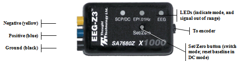
Note: EEG practitioners call the negative electrode "reference" and the positive electrode "signal".
Sensor modes
The EEG-Z3 can operate in any of three modes: regular EEG mode (2 Hz – 1 kHz), low frequency mode (0.01 Hz – 1 kHz) and DC mode (0 Hz – 1 kHz). Modes can be changed on-the-fly. To change the sensor mode:
- Press and hold the Set/Zero button for about 3 seconds. The LED lights will begin to cycle through the 3 modes.
- Release the Set/Zero button when the LED lights up for the mode you want to use.
EEG mode
Depending on the application, this mode may require software methods to zero the sensor (remove the offset, or non-zero baseline) prior to first time use. Note that most applications involving signal processing of EEG do not include the very low frequency content of the signal, and this offset removal may not be necessary. It may be necessary when the raw EEG is displayed. To achieve this, a zeroing cable is provided with the sensor.
EP/0.01 Hz mode When you first enter this mode, a settling period is imposed during which the signal returns from an out-of-range value to the baseline. This normally requires approximately 100 seconds, as it is based on the time constant of the system in this mode. This mode is sensitive to both eye and head movement, and care should be taken to minimize both actions during sessions in this mode.
SCP/DC mode As is to be expected with DC measurements, in this mode the EEG-Z3 is subject to the DC drift of the system. Even with special care taken to reduce electrode polarization, an initial period of polarization is unavoidable. For this reason, after the initial placement of electrodes on the subject, a "settling time" of 10 to 20 minutes is usually necessary before beginning a recording.
In SCP/DC mode, when the LED blinks to indicate that the signal is approaching the limits of the sensor's range, you can use the Set/Zero button to bring the signal back to the baseline again.
Selecting alternative baselines in SCP/DC mode:
The Zero function in this mode is necessary to operate in the presence of DC drift. Since drift tends to be in one direction, there are three baseline levels that you can choose from:
- If the signal is drifting UP, select Low. This will place the baseline in the lower half of the sensor range, toward the bottom.
- If the signal is drifting DOWN, select High. This will place the baseline in the upper half of the sensor range, toward the top.
- If signal drift is minimal, OR is up and down, OR you don't know the direction of drift, select Middle. This will place the baseline close to 0. This is the default baseline setting.
This selection is made by double clicking the Set/Zero button. Each time you double click, the levels will cycle in the following order: High (Up), Low (Down), and Zero, such that you may select the desired baseline level. Once selected, zeroing the sensor by pressing the Set/Zero button once will return the signal to this baseline. The sensor resets its baseline to the default level (Middle) when it is powered off.
Sensor Placement
International 10-20 system for placement [1] is recommended. Skin preparation and use of adhesive, conductive gel is also most often recommended for best results.
 Skin preparation: For any recording where signal quality matters, good skin preparation is important to get a clean signal and avoid artifacts. Before applying the EEG electrodes, use a skin preparation cream, such as NuPrep. If necessary, shaving excess body hair may be required (see instructions below).
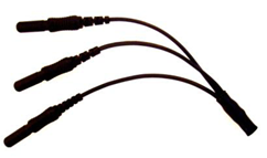
Electrode Selection: The DIN connectors allow any EEG electrode with 1.5 mm standard DIN connector to be connected to the EEG-Z3 sensor. For single channel recordings, three (3) electrodes will be needed (one active, one reference and one ground). When recording multiple channels simultaneously, jumper cables such as SA9315-2 and SA9315-4 can be used to allow a single electrode to be used as a common reference and/or common ground. This reduces the number of electrodes needed. This sensor must be used with sintered silver-silver/chloride electrodes to ensure proper performance.
![]() Good Electrode Contact: Conductive gel is required for optimal electrode-skin contact. Make sure the electrodes are placed firmly on the skin and that there is good contact between skin and electrode (see instructions below).
Good Electrode Contact: Conductive gel is required for optimal electrode-skin contact. Make sure the electrodes are placed firmly on the skin and that there is good contact between skin and electrode (see instructions below).
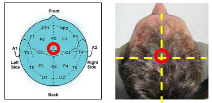
10-20 electrode placement system The electroencephalogram (EEG) is a recording of the electrical activity of the brain, most often captured at the surface of the scalp. The ten-twenty (10-20) electrode system of the International Federation [1] is the standard for electrode placement. It is used to place surface EEG electrodes in a repeatable way independent of inter-subject anatomical variability.
It is called 10-20 because of the way distances between electrode sites are computed. The distances between certain anatomical landmarks are segmented at increments of 10% and 20% of their value, and electrodes are placed at these points.
The sites are named as follows:
- A letter is used to indicate over which area of the brain the site is located. These are:
-
- F: frontal lobe
- FP: frontopolar area
- C: central sulcus
- T: temporal lobe
- P: parietal lobe
- O: occipital lobe
- Other miscellaneous labels are used for the ears (A) and other reference sites (for example, M for mastoid process, G for ground, etc…)
- The letter Z is used to indicate the central line along the interhemispheric fissure.
- A number is used to indicate the position in reference to the central line (Z).
-
- Odd numbers are on the left
- Even numbers are on the right
- The number value increases the further away the site is from the central line
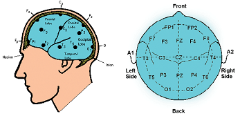
For example, along the line joining sites A1 and A2: to the right of A1, at 10% of the overall A1-A2 distance is electrode site T3. This is followed by C3 (20% further), Cz (20% further), C4 (20% further), and T4 (20% further). Site T4 should fall 10% to the left of A2.
EEG electrodes
For one channel EEG recordings, only one T8770 or T8775 kit is required.
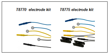
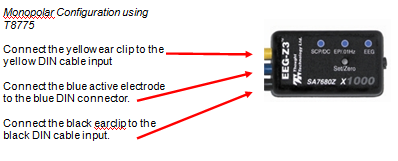
Note: For bipolar configuration, the yellow cup electrode is used in place of the yellow earclip.
Note: For mastoid instead of ear reference, electrode kit T8770 can be used.
EEG electrode placement technique
Proper site preparation and electrode placement are essential for clean, trouble-free recording of the EEG signal. The following steps describe how to achieve a secure connection in an efficient, repeatable way. They should be followed closely every time the EEG signal is recorded. This may seem daunting at first, but the technique is easily learned and the user will quickly become accustomed to it and will certainly appreciate the benefits.
- Locate the required electrode sites
(In this example the site Cz will be used.)
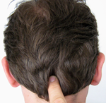 Locate the Inion. On the posterior base of the skull, where the spine meets the skull, there is a small protrusion called the “inion”. It can be found by running the finger up the spine towards the skull.
- There is a small crevice between the spine and skull in which vertebrae can no longer be felt. Just above that area, the inion of the skull can be found.
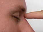 Locate the nasion. The depression on the bridge of the nose, just below the brow and directly between both eyes, is called the “nasion”.
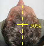 The line between these two points runs along the interhemispheric fissure of the brain (the space that separates the left and right sides of the brain, i.e. right down the middle).
Mark a spot located at 50% of the distance between the nasion and the inion.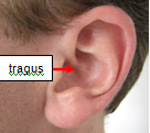 Locate the mandibular notch.
Anatomy revisited: To locate the mandibular notch, place a finger against the tragus, just anterior to the ear, and ask the subject to open their mouth. Your finger should find its way into a cavity, resting superior to the manibular notch.
Find this spot on both sides of the head.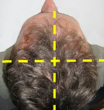 The line that connects the left and right mandibular arches runs along the central sulcus of the brain (the space that separates the frontal and parietal lobes).
- Mark a spot located at 50% of the distance between the left and right mandibular notches. It should intersect directly with the mark made between the front and back of the head.
- The intersection of these two lines is electrode location Cz.
Note: Electrode location CZ can always be approximated instead of explicitly measured following the procedure described above. It is the top middle of the skull. Imagine if the subject were to hang perfectly straight from a string tied to the top of their heads, this is where the string would have to be fixed. Still, to ensure repeatable measurements, especially when comparing across sessions, it is recommended that the electrode locations be measured as described.
- Prepare the scalp
The scalp must be prepared before an electrode can be fixed. This involves slightly abrading the skin to remove dead skin, sweat and other contaminants to the EEG signal.
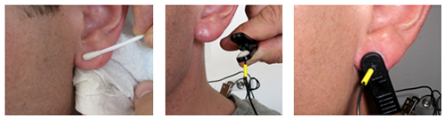
 Scoop up a small quantity of NuPrep™ skin prepping gel on a cotton swab or tissue.
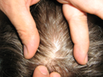 With the thumb and index finger of one hand, separate the hair around the electrode site that was previously found and marked.
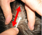 Run the gel in the direction of the natural line formed along the scalp by the split hair. Some light force must be used, enough to redden the scalp slightly, but not enough to break the skin.
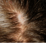 Wipe away the excess prepping gel with a dry, lint-free cloth. Care should be taken to keep the hair parted and to keep track of the site after wiping clean.
Helpful trick: A small amount of Ten20™ Conductive paste should be smeared on the newly prepared site. This has the combined effect of keeping track of the site, keeping the hair neatly out of the way, and acting as a landing pad for the electrode once it is ready to fix.
- Prepare the electrodes
- Start by securing the electrode cables to the subject.
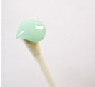
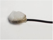 Add Ten20TM paste onto the disc electrode, just enough to form a ball on the face of the disc and to ensure that the entire surface is covered with paste, but not so much that it spills over the edge. Shown is the ideal amount of paste.
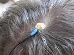 Add Ten20TM paste onto the disc electrode, just enough to form a ball on the face of the disc and to ensure that the entire surface is covered with paste, but not so much that it spills over the edge. Shown is the ideal amount of paste.
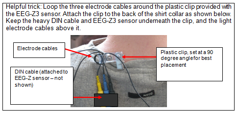
Helpful trick: Place the electrode so that the direction of the cable does not place undue stress on the cup (so that it gets pulled, lifted or twisted off). The cable should hang naturally and towards the plastic clip (as shown). Leave enough slack in the cable to allow for comfortable head movement as well.
- Reference sites.
When using electrode kit T8775, repeat the above preparation and placement steps on the ear lobes. Do not put too much Ten20 TM paste on the ear clip electrode, but ensure that the electrode pellet is completely covered.
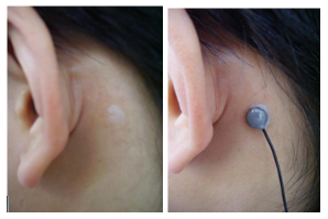
Mastoid placement using electrode kit T8770 is similar. Locate the mastoid process behind the ear and prepare the skin as described above. Leave a small quantity of Ten20 TM paste on the prepared site to mark the spot. Prepare the paste on the reference electrode the same way as for the active electrode, described above, and gently place on the prepared site as described above for the active electrode.
Leave enough slack in the cable to allow the subject to turn their head easily, but not too much that it can get caught. Think about the angle of the cable from the ear clip to the neck clip, so that no extra tension is placed on the ear clip.
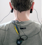 Viewed from behind, the final configuration should look like this:
Note the position of the clip, the direction of the cables and the slack left to provide mobility.
(EEG-Z sensor SA9305Z and interface connector SA8740 shown here, procedure is similar for EEG-Z3 sensor)
References [1] H.H. Jasper, “The ten-twenty electrode system of the International Federation”, Electroencephalography and Clinical Neurophysiology, vol. 10, pp. 370-375, 1958.
Technical Specifications
- Input impedance : Differential: 100GΩ paralleled with 270pF
Common-mode: 100GΩ paralleled with 200pF - Signal input range : 0 –200µV
- Noise : < 0.5 µVRMS
- CMRR (excluding CM signal active cancellation) : >100dB
- CM active cancellation effect : > 40dB @10-120Hz)
- Accuracy : ≤ 1%, ±0.3µVRMS
- Electrode offset tolerance (Slow AC and DC modes) : ±100mV
- Bandwidth, lower cutoff, 3dB EP/.01Hz : ±100mV
- Bandwidth, lower cutoff, 3dB, EEG mode : 1.5Hz
- Bandwidth, upper 3dB (all modes) : 1600KHz
Electrical Compatibility
The EEG-Z3 sensor is designed to coexist with other Thought Technology bio potential sensors such as T9306M(or T9307M) EKG sensor, T9303M MyoScan sensor, T9305M EEG sensor, or SA9309M Skin Conductance sensor.
To ensure correct EEG-Z3 sensor operation, if sensors from another manufacturer are in the same electrical circuit and connected to the same subject, their electrodes must function at a voltage within the specified operating bias range, 1.0 to 3.0 volts above sensor ground. To check whether another sensor is interfering with the EEG-Z3 sensor operation, connect and disconnect the other sensor from the subject, and note whether this causes a change in the EEG-Z3 sensor signal level, or whether connection of the other sensor appears to cause any signal artifacts in the EEG-Z3 signal.
Interfacing with 3rd Party Data Acquisition Systems
Recommended Connectivity for Electrical Safety
Thought Technology recommends the use of TT Sensor Isolator ST9405AM when interfacing patient connected sensor(s) to line powered equipment(s) or devices.
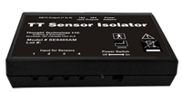 The TT Sensor Isolator ST9405AM is an interface device providing medical grade electrical isolation between the patient connected sensors and the acquisition system. It provides the equivalent of Two Means of Patient Protection under IEC 60601-1, and supplies battery power to the sensors. Using this device ensures Thought Technology sensors are safely interfaced to the analog inputs of line-powered systems such as computers with DAQ cards.
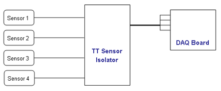
Note that this device isolates only between sensors and the DAQ interface, not between different sensor channels.
The TT Sensor Isolator can interface up to 4 sensors to a DAQ card. TT Sensor Isolator can be connected to the DAQ card in two ways:
- via two stereo jacks, or
- via a DB-15 connector; a BNC interface cable (SA9409BNC) or a pigtail cable (SA9409PGT) can be provided with the unit.
For more detailed information on the Sensor Isolator 4∞, consult the Thought Technology Science Division website or contact the sales department or your distributor.
Division website or contact the sales department or your distributor.
Direct Connectivity for Electrically Isolated Systems
The following notes are provided for qualified users to directly interface Thought Technology sensors with external systems.
WARNING: If the sensor is interfaced to non-Thought Technology devices without the use of a TT Sensor Isolator SE9405AM, an elevated risk of electrical shock may be present. In particular, if a patient-connected sensor is connected to any line powered device(s) or equipment(s), it will be the responsibility of the qualified user to ensure the electrical safety in the setup and to ensure that the device or equipment provides sufficient isolation.
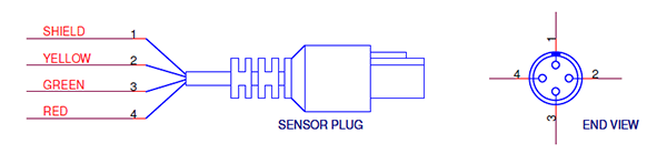
To interface with a sensor, a single sensor cable may be cut in half. Both sides can then be used to make custom interfacing cables by stripping the outer insulation of each required conductor. The sensor cable contains 4 color coded conductors. The table below shows the color coding and pin connector assignment.
| Pin | Color Code | Function | Note |
| 1 | metal (shield) | ground | Signal and power ground, connection required. |
| 2 | yellow | auxiliary (sensor ID) | No connection required. |
| 3 | green | signal | Sensor output signal |
| 4 | red | sensor power | Supply voltage, +7.26V referenced to ground. Note: sensor performance may be sensitive to supply voltage. |
Notes:
1. The nominal supply voltage for this sensor is 7.26V. The sensor can safely be used with a supply voltage of up to 9V.
Recommended Specifications for DAQ Hardware
- Recommended resolution of 0.15mV (16-bit ADC over 10V span) or better
- Minimum input range:
- If connected via SE9405AM Sensor Isolator, choose 0-5V (unipolar) or ±5V (bipolar).
- If directly connected to DAQ, choose ±5V (bipolar).
Simplified Transfer Function
![]() Conversion of measured input voltage (raw EEG signal) to sensor output voltage (to DAQ)
Conversion of measured input voltage (raw EEG signal) to sensor output voltage (to DAQ)
 Conversion of sensor output voltage (to DAQ) to measured input voltage (raw EEG signal)
Specification Summaries Of Supported Accessories / Hardware
Table below lists Thought Technology accessories for the EEG-Z3 Sensor.
| Accessory |
Product Number |
|||||||||||||||
 |
DC-EEG Three Disc Electrode (T8770) Ideal for reference and active ground placement on the mastoid process. Can be used in monopolar or bipolar configuration.
|
|||||||||||||||
 |
Monopolar / Bipolar kit (T8775) This kit allows users to make either monopolar or bipolar single channel measurements using ear clip reference electrodes.
|
|||||||||||||||
 |
DC-EEG Ag/AgCl Disc Electrode (SA7675) Available in black (SA7675), white (SA7675W), and blue (SA7675B). |
|||||||||||||||
 |
DC-EEG Ag/AgCl Ear Clip (SA9322) Available in black (SA9322) and yellow (SA9322Y). |
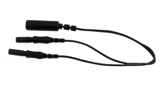 |
1M2F Y-Connector (SA9315) Connects a single electrode to two inputs. Allows use of the same electrode in two channels for common ground or reference. |
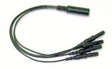 |
1M4F Y-Connector (SA9315-4) Connects a single electrode to four inputs. Allows use of the same electrode in up to four channels for common ground or reference. |
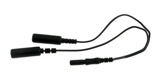 |
2M1F Y-Connector (SA9319) Connects two electrodes to a single input. Used to join two ear clip cables together to form a linked ear reference. |
Product Overview
The EEG-Z3 sensor is an electroencephalograph sensor, or pre-amplifier, for measuring the brain’s electrical activity from the surface of the scalp. It amplifies the small electrical voltages that are generated by the neurological activity of the brain. It includes DIN input connectors for use with standard EEG electrodes.
Note: EEG practitioners call the negative electrode "reference" and the positive electrode "signal".
Sensor modes
The EEG-Z3 can operate in any of three modes: regular EEG mode (2 Hz – 1 kHz), low frequency mode (0.01 Hz – 1 kHz) and DC mode (0 Hz – 1 kHz). Modes can be changed on-the-fly. To change the sensor mode:
- Press and hold the Set/Zero button for about 3 seconds. The LED lights will begin to cycle through the 3 modes.
- Release the Set/Zero button when the LED lights up for the mode you want to use.
EEG mode
Depending on the application, this mode may require software methods to zero the sensor (remove the offset, or non-zero baseline) prior to first time use. Note that most applications involving signal processing of EEG do not include the very low frequency content of the signal, and this offset removal may not be necessary. It may be necessary when the raw EEG is displayed. To achieve this, a zeroing cable is provided with the sensor.
EP/0.01 Hz mode When you first enter this mode, a settling period is imposed during which the signal returns from an out-of-range value to the baseline. This normally requires approximately 100 seconds, as it is based on the time constant of the system in this mode. This mode is sensitive to both eye and head movement, and care should be taken to minimize both actions during sessions in this mode.
SCP/DC mode As is to be expected with DC measurements, in this mode the EEG-Z3 is subject to the DC drift of the system. Even with special care taken to reduce electrode polarization, an initial period of polarization is unavoidable. For this reason, after the initial placement of electrodes on the subject, a "settling time" of 10 to 20 minutes is usually necessary before beginning a recording.
In SCP/DC mode, when the LED blinks to indicate that the signal is approaching the limits of the sensor's range, you can use the Set/Zero button to bring the signal back to the baseline again.
Selecting alternative baselines in SCP/DC mode:
The Zero function in this mode is necessary to operate in the presence of DC drift. Since drift tends to be in one direction, there are three baseline levels that you can choose from:
- If the signal is drifting UP, select Low. This will place the baseline in the lower half of the sensor range, toward the bottom.
- If the signal is drifting DOWN, select High. This will place the baseline in the upper half of the sensor range, toward the top.
- If signal drift is minimal, OR is up and down, OR you don't know the direction of drift, select Middle. This will place the baseline close to 0. This is the default baseline setting.
This selection is made by double clicking the Set/Zero button. Each time you double click, the levels will cycle in the following order: High (Up), Low (Down), and Zero, such that you may select the desired baseline level. Once selected, zeroing the sensor by pressing the Set/Zero button once will return the signal to this baseline. The sensor resets its baseline to the default level (Middle) when it is powered off.
Sensor Placement
International 10-20 system for placement [1] is recommended. Skin preparation and use of adhesive, conductive gel is also most often recommended for best results.
Skin preparation: For any recording where signal quality matters, good skin preparation is important to get a clean signal and avoid artifacts. Before applying the EEG electrodes, use a skin preparation cream, such as NuPrep. If necessary, shaving excess body hair may be required (see instructions below).
Electrode Selection: The DIN connectors allow any EEG electrode with 1.5 mm standard DIN connector to be connected to the EEG-Z3 sensor. For single channel recordings, three (3) electrodes will be needed (one active, one reference and one ground). When recording multiple channels simultaneously, jumper cables such as SA9315-2 and SA9315-4 can be used to allow a single electrode to be used as a common reference and/or common ground. This reduces the number of electrodes needed. This sensor must be used with sintered silver-silver/chloride electrodes to ensure proper performance.
![]() Good Electrode Contact: Conductive gel is required for optimal electrode-skin contact. Make sure the electrodes are placed firmly on the skin and that there is good contact between skin and electrode (see instructions below).
Good Electrode Contact: Conductive gel is required for optimal electrode-skin contact. Make sure the electrodes are placed firmly on the skin and that there is good contact between skin and electrode (see instructions below).
10-20 electrode placement system The electroencephalogram (EEG) is a recording of the electrical activity of the brain, most often captured at the surface of the scalp. The ten-twenty (10-20) electrode system of the International Federation [1] is the standard for electrode placement. It is used to place surface EEG electrodes in a repeatable way independent of inter-subject anatomical variability.
It is called 10-20 because of the way distances between electrode sites are computed. The distances between certain anatomical landmarks are segmented at increments of 10% and 20% of their value, and electrodes are placed at these points.
The sites are named as follows:
- A letter is used to indicate over which area of the brain the site is located. These are:
-
- F: frontal lobe
- FP: frontopolar area
- C: central sulcus
- T: temporal lobe
- P: parietal lobe
- O: occipital lobe
- Other miscellaneous labels are used for the ears (A) and other reference sites (for example, M for mastoid process, G for ground, etc…)
- The letter Z is used to indicate the central line along the interhemispheric fissure.
- A number is used to indicate the position in reference to the central line (Z).
-
- Odd numbers are on the left
- Even numbers are on the right
- The number value increases the further away the site is from the central line
For example, along the line joining sites A1 and A2: to the right of A1, at 10% of the overall A1-A2 distance is electrode site T3. This is followed by C3 (20% further), Cz (20% further), C4 (20% further), and T4 (20% further). Site T4 should fall 10% to the left of A2.
EEG electrodes
For one channel EEG recordings, only one T8770 or T8775 kit is required.
Note: For bipolar configuration, the yellow cup electrode is used in place of the yellow earclip.
Note: For mastoid instead of ear reference, electrode kit T8770 can be used.
EEG electrode placement technique
Proper site preparation and electrode placement are essential for clean, trouble-free recording of the EEG signal. The following steps describe how to achieve a secure connection in an efficient, repeatable way. They should be followed closely every time the EEG signal is recorded. This may seem daunting at first, but the technique is easily learned and the user will quickly become accustomed to it and will certainly appreciate the benefits.
- Locate the required electrode sites
(In this example the site Cz will be used.)
- Locate the Inion. On the posterior base of the skull, where the spine meets the skull, there is a small protrusion called the “inion”. It can be found by running the finger up the spine towards the skull.
- There is a small crevice between the spine and skull in which vertebrae can no longer be felt. Just above that area, the inion of the skull can be found.
- Locate the nasion. The depression on the bridge of the nose, just below the brow and directly between both eyes, is called the “nasion”.
- The line between these two points runs along the interhemispheric fissure of the brain (the space that separates the left and right sides of the brain, i.e. right down the middle).
Mark a spot located at 50% of the distance between the nasion and the inion. - Locate the mandibular notch.
Anatomy revisited: To locate the mandibular notch, place a finger against the tragus, just anterior to the ear, and ask the subject to open their mouth. Your finger should find its way into a cavity, resting superior to the manibular notch.
Find this spot on both sides of the head. - The line that connects the left and right mandibular arches runs along the central sulcus of the brain (the space that separates the frontal and parietal lobes).
- Mark a spot located at 50% of the distance between the left and right mandibular notches. It should intersect directly with the mark made between the front and back of the head.
- The intersection of these two lines is electrode location Cz.
Note: Electrode location CZ can always be approximated instead of explicitly measured following the procedure described above. It is the top middle of the skull. Imagine if the subject were to hang perfectly straight from a string tied to the top of their heads, this is where the string would have to be fixed. Still, to ensure repeatable measurements, especially when comparing across sessions, it is recommended that the electrode locations be measured as described.
- Prepare the scalp
The scalp must be prepared before an electrode can be fixed. This involves slightly abrading the skin to remove dead skin, sweat and other contaminants to the EEG signal.
- Scoop up a small quantity of NuPrep™ skin prepping gel on a cotton swab or tissue.
- With the thumb and index finger of one hand, separate the hair around the electrode site that was previously found and marked.
- Run the gel in the direction of the natural line formed along the scalp by the split hair. Some light force must be used, enough to redden the scalp slightly, but not enough to break the skin.
- Wipe away the excess prepping gel with a dry, lint-free cloth. Care should be taken to keep the hair parted and to keep track of the site after wiping clean.
Helpful trick: A small amount of Ten20™ Conductive paste should be smeared on the newly prepared site. This has the combined effect of keeping track of the site, keeping the hair neatly out of the way, and acting as a landing pad for the electrode once it is ready to fix.
- Prepare the electrodes
- Start by securing the electrode cables to the subject.
- Add Ten20TM paste onto the disc electrode, just enough to form a ball on the face of the disc and to ensure that the entire surface is covered with paste, but not so much that it spills over the edge. Shown is the ideal amount of paste.
- Add Ten20TM paste onto the disc electrode, just enough to form a ball on the face of the disc and to ensure that the entire surface is covered with paste, but not so much that it spills over the edge. Shown is the ideal amount of paste.
Helpful trick: Place the electrode so that the direction of the cable does not place undue stress on the cup (so that it gets pulled, lifted or twisted off). The cable should hang naturally and towards the plastic clip (as shown). Leave enough slack in the cable to allow for comfortable head movement as well.
- Reference sites.
When using electrode kit T8775, repeat the above preparation and placement steps on the ear lobes. Do not put too much Ten20 TM paste on the ear clip electrode, but ensure that the electrode pellet is completely covered.
Mastoid placement using electrode kit T8770 is similar. Locate the mastoid process behind the ear and prepare the skin as described above. Leave a small quantity of Ten20 TM paste on the prepared site to mark the spot. Prepare the paste on the reference electrode the same way as for the active electrode, described above, and gently place on the prepared site as described above for the active electrode.
Leave enough slack in the cable to allow the subject to turn their head easily, but not too much that it can get caught. Think about the angle of the cable from the ear clip to the neck clip, so that no extra tension is placed on the ear clip.
Viewed from behind, the final configuration should look like this:
Note the position of the clip, the direction of the cables and the slack left to provide mobility.
(EEG-Z sensor SA9305Z and interface connector SA8740 shown here, procedure is similar for EEG-Z3 sensor)
References [1] H.H. Jasper, “The ten-twenty electrode system of the International Federation”, Electroencephalography and Clinical Neurophysiology, vol. 10, pp. 370-375, 1958.
Technical Specifications
- Input impedance : Differential: 100GΩ paralleled with 270pF
Common-mode: 100GΩ paralleled with 200pF - Signal input range : 0 –200µV
- Noise : < 0.5 µVRMS
- CMRR (excluding CM signal active cancellation) : >100dB
- CM active cancellation effect : > 40dB @10-120Hz)
- Accuracy : ≤ 1%, ±0.3µVRMS
- Electrode offset tolerance (Slow AC and DC modes) : ±100mV
- Bandwidth, lower cutoff, 3dB EP/.01Hz : ±100mV
- Bandwidth, lower cutoff, 3dB, EEG mode : 1.5Hz
- Bandwidth, upper 3dB (all modes) : 1600KHz
Electrical Compatibility
The EEG-Z3 sensor is designed to coexist with other Thought Technology bio potential sensors such as T9306M(or T9307M) EKG sensor, T9303M MyoScan sensor, T9305M EEG sensor, or SA9309M Skin Conductance sensor.
To ensure correct EEG-Z3 sensor operation, if sensors from another manufacturer are in the same electrical circuit and connected to the same subject, their electrodes must function at a voltage within the specified operating bias range, 1.0 to 3.0 volts above sensor ground. To check whether another sensor is interfering with the EEG-Z3 sensor operation, connect and disconnect the other sensor from the subject, and note whether this causes a change in the EEG-Z3 sensor signal level, or whether connection of the other sensor appears to cause any signal artifacts in the EEG-Z3 signal.
Interfacing with 3rd Party Data Acquisition Systems
Recommended Connectivity for Electrical Safety
Thought Technology recommends the use of TT Sensor Isolator ST9405AM when interfacing patient connected sensor(s) to line powered equipment(s) or devices.
The TT Sensor Isolator ST9405AM is an interface device providing medical grade electrical isolation between the patient connected sensors and the acquisition system. It provides the equivalent of Two Means of Patient Protection under IEC 60601-1, and supplies battery power to the sensors. Using this device ensures Thought Technology sensors are safely interfaced to the analog inputs of line-powered systems such as computers with DAQ cards.
Note that this device isolates only between sensors and the DAQ interface, not between different sensor channels.
The TT Sensor Isolator can interface up to 4 sensors to a DAQ card. TT Sensor Isolator can be connected to the DAQ card in two ways:
- via two stereo jacks, or
- via a DB-15 connector; a BNC interface cable (SA9409BNC) or a pigtail cable (SA9409PGT) can be provided with the unit.
For more detailed information on the Sensor Isolator 4∞, consult the Thought Technology Science Division website or contact the sales department or your distributor.
Division website or contact the sales department or your distributor.
Direct Connectivity for Electrically Isolated Systems
The following notes are provided for qualified users to directly interface Thought Technology sensors with external systems.
WARNING: If the sensor is interfaced to non-Thought Technology devices without the use of a TT Sensor Isolator SE9405AM, an elevated risk of electrical shock may be present. In particular, if a patient-connected sensor is connected to any line powered device(s) or equipment(s), it will be the responsibility of the qualified user to ensure the electrical safety in the setup and to ensure that the device or equipment provides sufficient isolation.
To interface with a sensor, a single sensor cable may be cut in half. Both sides can then be used to make custom interfacing cables by stripping the outer insulation of each required conductor. The sensor cable contains 4 color coded conductors. The table below shows the color coding and pin connector assignment.
| Pin | Color Code | Function | Note |
| 1 | metal (shield) | ground | Signal and power ground, connection required. |
| 2 | yellow | auxiliary (sensor ID) | No connection required. |
| 3 | green | signal | Sensor output signal |
| 4 | red | sensor power | Supply voltage, +7.26V referenced to ground. Note: sensor performance may be sensitive to supply voltage. |
Notes:
1. The nominal supply voltage for this sensor is 7.26V. The sensor can safely be used with a supply voltage of up to 9V.
Recommended Specifications for DAQ Hardware
- Recommended resolution of 0.15mV (16-bit ADC over 10V span) or better
- Minimum input range:
- If connected via SE9405AM Sensor Isolator, choose 0-5V (unipolar) or ±5V (bipolar).
- If directly connected to DAQ, choose ±5V (bipolar).
Simplified Transfer Function
![]() Conversion of measured input voltage (raw EEG signal) to sensor output voltage (to DAQ)
Conversion of measured input voltage (raw EEG signal) to sensor output voltage (to DAQ)
Conversion of sensor output voltage (to DAQ) to measured input voltage (raw EEG signal)
Specification Summaries Of Supported Accessories / Hardware
Table below lists Thought Technology accessories for the EEG-Z3 Sensor.
| Accessory |
Product Number |
|||||||||||||||
|
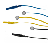
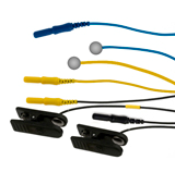
DC-EEG Three Disc Electrode (T8770) Ideal for reference and active ground placement on the mastoid process. Can be used in monopolar or bipolar configuration.
|
|||||||||||||||
|
Monopolar / Bipolar kit (T8775) This kit allows users to make either monopolar or bipolar single channel measurements using ear clip reference electrodes.
|
|||||||||||||||
|
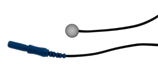
DC-EEG Ag/AgCl Disc Electrode (SA7675) Available in black (SA7675), white (SA7675W), and blue (SA7675B). |
|||||||||||||||
|
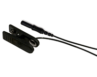
DC-EEG Ag/AgCl Ear Clip (SA9322) Available in black (SA9322) and yellow (SA9322Y). |
|
1M2F Y-Connector (SA9315) Connects a single electrode to two inputs. Allows use of the same electrode in two channels for common ground or reference. |
|
1M4F Y-Connector (SA9315-4) Connects a single electrode to four inputs. Allows use of the same electrode in up to four channels for common ground or reference. |
|
2M1F Y-Connector (SA9319) Connects two electrodes to a single input. Used to join two ear clip cables together to form a linked ear reference. |
Technical Specifications
| Input impedance :Differential: 100GΩ paralleled with 270pF |
| Common-mode :100GΩ paralleled with 200pF |
| Signal input range :0 –200µV |
| Noise : < 0.5 µVRMS |
| CMRR (excluding CM signal active cancellation) : >100dB |
| CM active cancellation effect : > 40dB @10-120Hz) |
| Accuracy :≤ 1%, ±0.3µVRMS |
| Electrode offset tolerance (Slow AC and DC modes) :±100mV |
| Bandwidth, lower cutoff, 3dB EP/.01Hz : ±100mV |
| Bandwidth, lower cutoff, 3dB, EEG mode : 1.5Hz |
| Bandwidth, upper 3dB (all modes) : 1600KHz |
More Products to Consider
 TT Infra Sensor
Table of Contents
Suggested References